Improved structure of drum brake

A drum brake, a pair of technology, applied in the field of motorcycle and electric vehicle brake devices, can solve the problems of easy wear of brake cams, poor braking effect of drum brakes, and large sliding distance of vehicle brakes, etc.

Pending Publication Date: 2021-08-24
仇梅惠
View PDF0 Cites 0 Cited by
  • Summary
  • Abstract
  • Description
  • Claims
  • Application Information

AI Technical Summary

Problems solved by technology

[0003] The purpose of the present invention is to provide an improved structure of the drum brake, which changes the working mode of the original drum brake which uses the cam to directly drive the expansion of the brake shoe, and effectively improves the poor braking effect of the existing drum brake, the large sliding distance of the vehicle brake, and the large braking distance of the brake cam. Disadvantages of wear and tear

Method used


Image

  • Improved structure of drum brake
  • Improved structure of drum brake

Examples


Embodiment

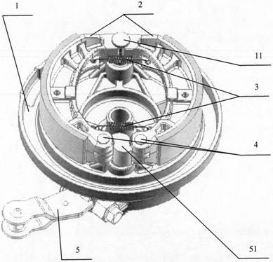
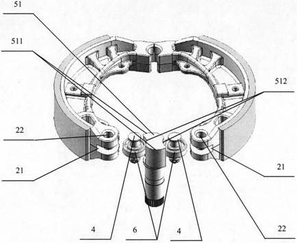
[0009] as attached figure 1 And attached figure 2 As shown, a pair of brake shoes (2) are installed in the housing (1), the elastic return element (3) is connected between the brake shoes (2), and one end of the pair of brake shoes (2) has a semicircle Arc surface, and is installed on the shaft (11), and can rotate around the shaft (11), and the shaft (11) is a part of the housing (1) structure; a pair of brake shoes (2) in the gap at the other end The components of the brake rocker arm assembly (5) are installed: the brake cam (51), the two sides of the brake cam (51) are respectively abutted with a bearing (6), and the bearing (6) is passed through by the rotating shaft (4) Its inner hole is installed in the shaft holes 22 of a pair of brake shoes (2), and when the brake rocker arm assembly (5) drives the brake cam (51) to rotate, the brake cam (51) drives the bearings on both sides (6) Rotate and move, and then drive a pair of brake shoes (2) to form an opening and closi...


PUM


Abstract

The invention discloses an improved structure of a drum brake. A pair of brake shoes is arranged in a drum brake shell, one ends of the brake shoes are rotationally positioned in the shell, an elastic reset element is connected between the brake shoes, a brake cam is arranged in an end gap of the other ends of the brake shoes, bearings are propped between the brake cam and the end surfaces of the brake shoes on the two sides correspondingly, and rotating shafts for the bearings are arranged in shaft holes of the pair of brake shoes. When a brake rocker arm assembly drives the brake cam to rotate, the two bearings are driven to rotate and move, then the pair of brake shoes is driven to form opening and closing movement, and therefore the brake function is achieved; and the outer contour surface of the brake cam is composed of two pairs of curved surfaces and four connecting cylindrical surfaces, the cross section lines of one pair of curved surfaces are convex circular involutes, the other pair of curved surfaces are concave cylindrical surfaces, and four corners formed by the two pairs of curved surfaces are connected through a section of convex cylindrical surface which is tangent to the two curved surfaces at the same time.

Description

technical field [0001] The invention belongs to the technical field of brake devices for motorcycles and electric vehicles. Background technique [0002] Drum brakes have been used as brake components on motorcycles and electric vehicles for nearly a century. Their structure generally consists of a housing, a pair of brake shoes, a brake cam, a brake rocker arm, and elastic reset elements. When braking, the brake rocker arm drives the brake cam to rotate, and the brake cam forces the brake shoe to expand and contact the housing to generate friction and then brake. After braking, rely on the elastic return element to pull the brake shoe back to its original position. During the braking process, in addition to the wear between the brake shoe and the housing, there will also be wear between the brake cam and the brake shoe, and the wear is always concentrated on several points or surfaces of the brake cam, which greatly shortens the brake life. In addition, the existing drum ...

Claims


Application Information

Patent Timeline
Patent Type & Authority Applications(China)
IPC IPC(8): F16D51/22F16D65/09F16D65/16F16D121/14F16D125/28
CPCF16D51/22F16D65/09F16D65/16F16D2065/1396F16D2121/14F16D2125/28
Inventor 仇梅惠戚文玉秦巍
Owner 仇梅惠
Why Eureka
Try Eureka