Liquid damper with damping force in direct proportion to displacement

A liquid damping and damping force technology, which is applied in the directions of liquid shock absorbers, shock absorbers, shock absorbers, etc., can solve the problems that the displacement of the piston rod of the damping force has no correlation, and the damping force cannot be generated, and achieves the change of the damping force, Simple and reasonable structure

Active Publication Date: 2021-08-24
CHANGZHOU UNIV
View PDF5 Cites 2 Cited by
  • Summary
  • Abstract
  • Description
  • Claims
  • Application Information

AI Technical Summary

Problems solved by technology

The damper in the prior art has certain disadvantages: it cannot generate a wide range of damping force, and the magnitude of the damping force has no correlation with the displacement of the piston rod

Method used


Image

  • Liquid damper with damping force in direct proportion to displacement
  • Liquid damper with damping force in direct proportion to displacement
  • Liquid damper with damping force in direct proportion to displacement

Examples


Embodiment Construction

[0020] The present invention will be further described in detail below in conjunction with the accompanying drawings and specific embodiments.

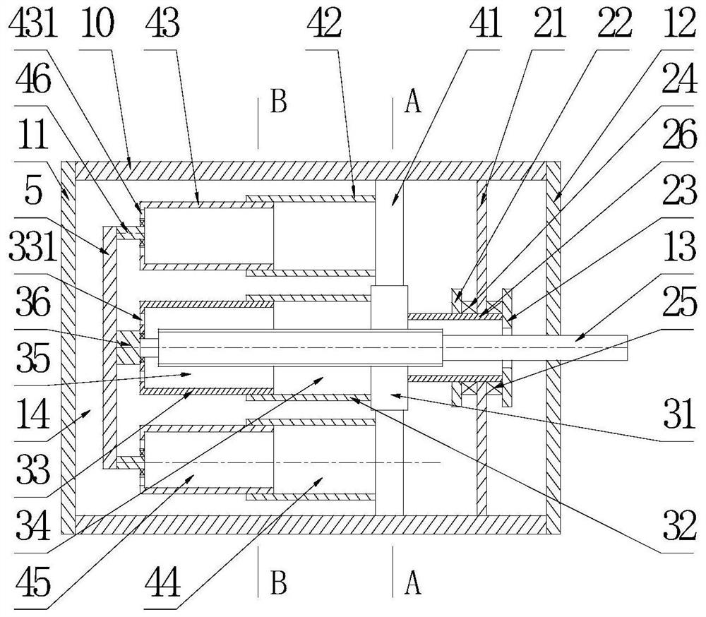
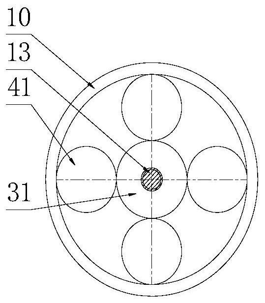
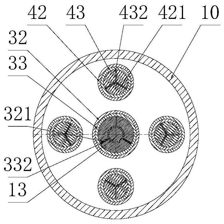
[0021] see figure 1 and figure 2 , a liquid damper in which the damping force is proportional to the displacement of the present invention, it includes a cylindrical hollow threaded cylinder 10 with internal threads on the inner wall, end caps A11 and end caps B12 installed at the left and right ends of the threaded cylinder 10, The left end is located inside the threaded cylinder 10 , and the right end extends through the end cover B12 to the threaded piston rod 13 outside the threaded cylinder 10 .

[0022] The middle part of the threaded piston rod 13 is provided with an external thread, and the two ends are polished rods; the inside of the threaded cylinder 10 is also equipped with a rotation damping device, four planetary damping devices with identical structures that can revolve around the rotation damping device, and a rotati...


PUM


Abstract

The invention discloses a liquid damper with damping force in direct proportion to displacement, and belongs to the technical field of liquid dampers. The liquid damper comprises a threaded cylinder body, an end cover A, an end cover B and a threaded piston rod. External threads are arranged in the middle of the threaded piston rod, and polish rods are arranged at the two ends of the threaded piston rod. A rotation damping device, four planetary damping devices and a gear axial positioning device are further arranged in the threaded cylinder body. The rotation damping device comprises a threaded gear, a U-shaped cylinder A and a U-shaped cylinder B. A fixed three-leaf plate A is arranged at the right end of the U-shaped cylinder A, and a sliding three-leaf plate A is arranged on the inner wall of the U-shaped cylinder B. The planetary damping device comprises a planetary gear, a U-shaped cylinder C and a U-shaped cylinder D. A fixed three-leaf plate B is arranged at the right end of the U-shaped cylinder C, and a sliding three-leaf plate B is arranged on the inner wall of the U-shaped cylinder D. According to the liquid damper, the structure is simple and reasonable, the damping force is changed by changing the volume and mass of the rotary motion damping liquid, and the damping force is in direct proportion to displacement.

Description

technical field [0001] The invention mainly relates to the technical field of liquid dampers, in particular to a liquid damper whose damping force is proportional to displacement. Background technique [0002] The liquid damper is an intelligent damping instrument with a wide range of applications. It uses the movement of the piston to make the damping fluid flow in the orifice to generate a damping force. Therefore, the adjustment of the damping force is mainly to change the flow or viscous absorption of the damping fluid. The damper in the prior art has certain disadvantages: it cannot generate a wide range of damping force, and the magnitude of the damping force has no correlation with the displacement of the piston rod. Therefore, it is very important to design a liquid damper whose damping force is proportional to the displacement of the piston rod and has a wide range of damping force. Contents of the invention [0003] The technical problem to be solved in the pres...

Claims


Application Information

Patent Timeline
IPC IPC(8): F16F9/16F16F9/48
CPCF16F9/16F16F9/48
Inventor 班书昊李晓艳何云松
Owner CHANGZHOU UNIV
Why Eureka
Try Eureka