A laser cycle test device and test method

A cycle test, laser technology, applied in the direction of measuring devices, photometry, optical radiation measurement, etc., can solve the problems of not being able to measure the laser energy of multiple laser energy generators at the same time, and low work efficiency, so as to shorten the overall working time, Improve work efficiency and improve efficiency

Active Publication Date: 2021-10-08
成都沃达惠康科技股份有限公司
View PDF10 Cites 0 Cited by
  • Summary
  • Abstract
  • Description
  • Claims
  • Application Information

AI Technical Summary

Problems solved by technology

[0002] The existing "laser energy testing device" such as CN201520058429.6 is composed of a collimating mirror and an energy meter, and only a collimating mirror and a protective mirror are added to the general laser energy meter. Like the general laser energy meter, the structure is simple, only Suitable for fixed test single laser generator energy
[0003] The current laser generator measurement device cannot measure the laser energy of multiple laser energy generators at the same time, and the work efficiency is low

Method used


Image

  • A laser cycle test device and test method
  • A laser cycle test device and test method
  • A laser cycle test device and test method

Examples


Embodiment 1

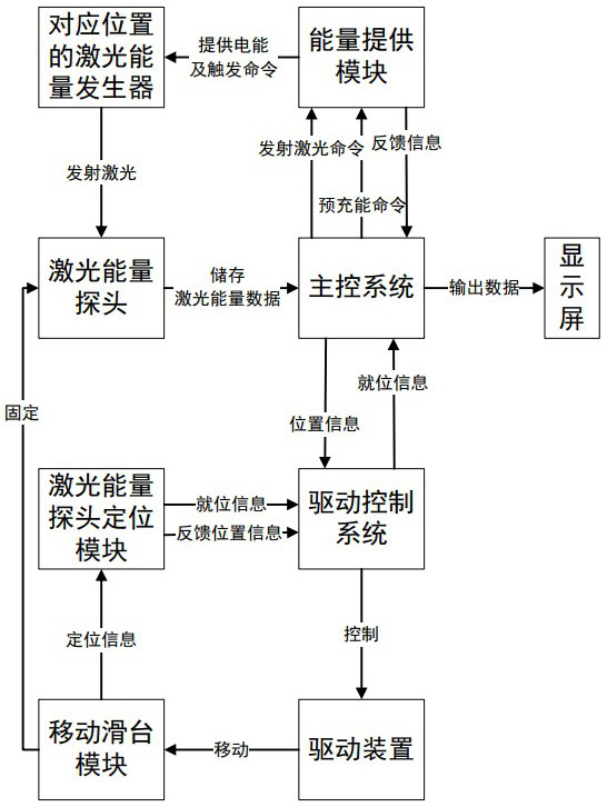
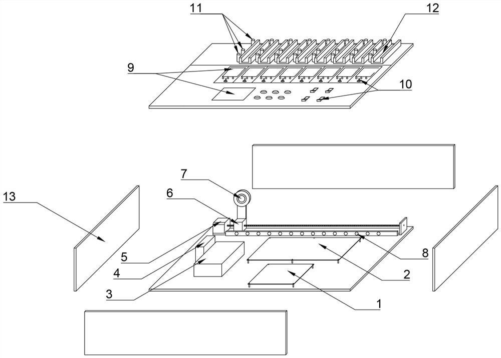
[0034] Such as figure 1 , figure 2 As shown, a laser cycle transmission system includes a mobile slide module 6 provided with a laser energy probe 7, the mobile slide module 6 is connected to a drive device 5, and the drive device 5 is electrically connected to a drive control system 4, which drives The control system 4 is used to transmit the stop signal to the drive device 5, the drive control system 4 is electrically connected to a laser energy probe positioning module 8, and the laser energy probe positioning module 8 is used to transmit the position information of the mobile slide module 6 to the drive control system 4, The drive control system 4 is electrically connected to the main control system 1 , the main control system 1 is used to transmit the position information to the drive control system 4 , and the drive control system 4 is used to transmit the position information of the mobile slide module 6 to the main control system 1 . The main control system 1 transmi...


PUM


Abstract

The invention discloses a laser circulation transmission system, a test device and a test method, wherein the laser circulation transmission system includes a mobile sliding table module provided with a laser energy probe, the mobile sliding table module is connected to a driving device, and the driving device is electrically powered. It is connected with a drive control system, the drive control system is electrically connected with a laser energy probe positioning module, and the drive control system is electrically connected with a main control system. The laser cycle energy management system includes an energy supply module for electrical connection with the main control system. The laser cycle test device includes the above-mentioned laser cycle transmission system and laser cycle energy management system, the energy supply module and the drive control system are all electrically connected to the main control system. Measure the laser energy of multiple laser energy generators by moving the laser energy probe. The invention can perform automatic cycle test on the laser energy emitted by a plurality of laser generators at the same time, and effectively improves the working efficiency of the batch laser energy test work.

Description

technical field [0001] The invention relates to the technical field of laser testing, in particular to a laser cycle testing device and a testing method. Background technique [0002] The existing "laser energy testing device" such as CN201520058429.6 is composed of a collimating mirror and an energy meter, and only a collimating mirror and a protective mirror are added to the general laser energy meter. Like the general laser energy meter, the structure is simple, only Suitable for stationary testing of a single laser generator energy. [0003] The current laser generator measurement device cannot measure the laser energy of multiple laser energy generators at the same time, and the working efficiency is low. Contents of the invention [0004] The purpose of the present invention is to provide a laser cycle test device and test method, which can automatically cycle test the laser energy emitted by multiple laser generators at the same time, effectively improving the work...

Claims


Application Information

Patent Timeline
Patent Type & Authority Patents(China)
IPC IPC(8): G01J1/00G01M11/02
CPCG01J1/00G01M11/02
Inventor 何军郑然
Owner 成都沃达惠康科技股份有限公司
Why Eureka
Try Eureka