

Unmanned obstacle avoidance driving method and terminal based on laser radar and UWB array
A technology of laser radar and driving method, applied in the direction of electromagnetic wave re-radiation, radio wave measurement system, utilization of re-radiation, etc., can solve the problems of mission failure, automatic obstacle avoidance, economic loss, etc. Reduce the effect of avoidance
- Summary
- Abstract
- Description
- Claims
- Application Information
AI Technical Summary
Problems solved by technology
Method used
Image

Examples
Embodiment 1
[0082] Please refer to figure 1 , image 3 and Figure 4 , Embodiment 1 of the present invention is:
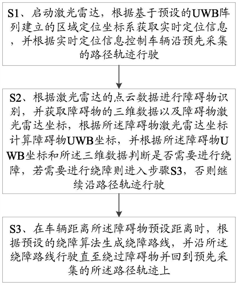
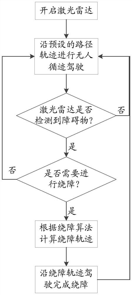
[0083] An unmanned obstacle avoidance driving method based on lidar and UWB array, comprising:
[0084] S1. Start the laser radar, obtain real-time positioning information according to the regional positioning coordinate system established based on the preset UWB array, and control the vehicle to drive along the pre-collected path track according to the real-time positioning information;
[0085] In this embodiment, the real-time positioning information includes real-time positioning coordinates and real-time heading angles, and obtaining real-time positioning information according to the regional positioning coordinate system established based on the preset UWB array is specifically: obtaining the vehicle and each of the The distance between the UWB base stations is to obtain the base station coordinates of the four nearest UWB base stations, and select two of the base st...
Embodiment 2
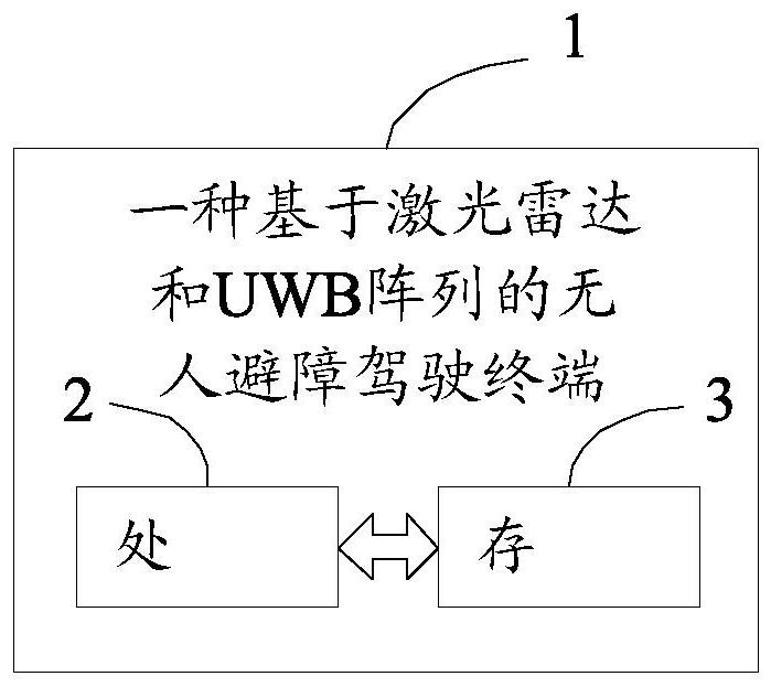
[0122] Please refer to figure 2 , the second embodiment of the present invention is:
[0123] An unmanned obstacle avoidance driving terminal 1 based on laser radar and UWB array, including a processor 2, a memory 3 and a computer program stored on the memory 3 and operable on the processor 2, the processor 2 executes the A computer program realizes the steps in the first embodiment above.
[0124] In summary, the present invention provides an unmanned obstacle-avoiding driving method and terminal based on lidar and UWB array, positioning is based on the regional positioning coordinate system established by the UWB array, and the UWB position of the obstacle is determined according to the lidar point cloud data. Coordinates and three-dimensional data, and judge whether the obstacle will cause harm to the vehicle according to the coordinates and three-dimensional data of the lidar, so as to realize the automatic obstacle avoidance of the unmanned driving of the vehicle, not o...
PUM
 Abstract
Description
Claims
Application Information