Supercharge Your Innovation With Domain-Expert AI Agents!

Stator core, motor, compressor and vehicle

A stator iron core and iron core technology, which is applied in the field of vehicles, can solve the problems of winding nozzle interference, affecting the performance of the motor, affecting the winding effect, etc.

Pending Publication Date: 2021-08-24
ANHUI WELLING AUTO PARTS CO LTD +1
View PDF0 Cites 5 Cited by
  • Summary
  • Abstract
  • Description
  • Claims
  • Application Information

AI Technical Summary

Problems solved by technology

The wall surface of the stator yoke of the segmented iron core 110' facing the axis of the stator iron core 100' is inclined, so that the joint 130' of two adjacent stator yokes forms a sharp angle, so that along the radial direction of the stator iron core 100', The size of the connection between two adjacent stator yokes is reduced, which affects the performance of the motor, and will interfere with the winding nozzle, affecting the winding effect

Method used


Image

  • Stator core, motor, compressor and vehicle
  • Stator core, motor, compressor and vehicle
  • Stator core, motor, compressor and vehicle

Examples


Embodiment 1

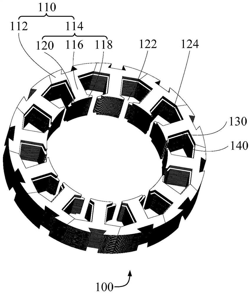
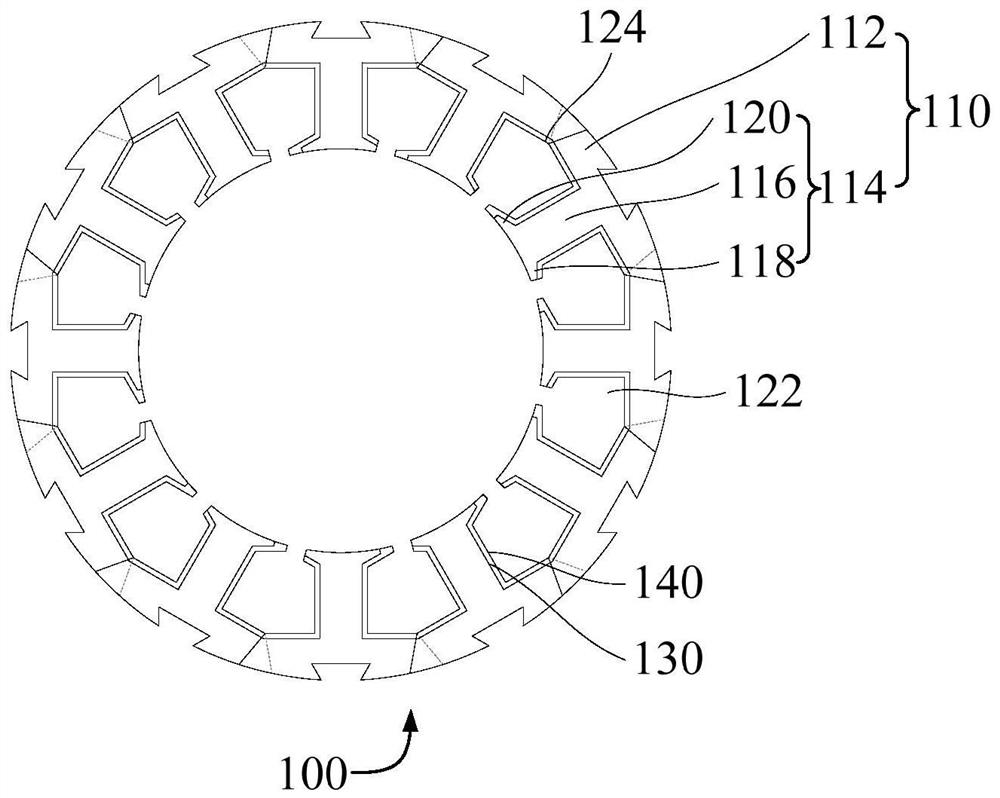
[0096] like figure 1 , figure 2 , image 3 , Figure 4 , Figure 5 , Figure 8 , Figure 11 and Figure 12 As shown, the embodiment of the first aspect of the present invention proposes a stator core 100, the stator core 100 includes a plurality of segmented iron cores 110, and the plurality of segmented iron cores 110 are connected end to end in turn around the axis of the stator core 100 , each segmented iron core 110 includes a plurality of stacked stamping sheets.

[0097] Each segmented iron core 110 includes a connected stator yoke 112 and stator teeth 114, the stator teeth 114 are located between the axes of the stator yoke 112 and the stator iron core 100, and the stator yokes 112 of any two adjacent segmented iron cores 110 The stator slot 122 is surrounded by the stator teeth 114 .

[0098] The wall surface of the stator yoke 112 facing the axis of the stator core 100 is a split surface 124 ; along the circumferential direction of the stator core 100 , at l...

Embodiment 2

[0107] like Figure 1 to Figure 5 , Figure 8 , Figure 11 and Figure 12 As shown, on the basis of Embodiment 1, Embodiment 2 provides a stator core 100, the stator core 100 includes a plurality of segmented iron cores 110, and the plurality of segmented iron cores 110 surround the axis of the stator core 100 Connected end to end in sequence, each segmented iron core 110 includes a plurality of stacked stampings.

[0108] Each segmented iron core 110 includes a connected stator yoke 112 and stator teeth 114, the stator teeth 114 are located between the axes of the stator yoke 112 and the stator iron core 100, and the stator yokes 112 of any two adjacent segmented iron cores 110 The stator slot 122 is surrounded by the stator teeth 114 .

[0109] The wall surface of the stator yoke 112 facing the axis of the stator core 100 is a split surface 124 ; along the circumferential direction of the stator core 100 , at least a part of the connection between the split surfaces 124 ...

Embodiment 3

[0119] like Figure 1 to Figure 5 , Figure 8 , Figure 11 and Figure 12 As shown, on the basis of any of the above embodiments, Embodiment 3 provides a stator core 100, the stator core 100 includes a plurality of segmented iron cores 110, and the plurality of segmented iron cores 110 wind around the stator core 100 The axis lines are connected end to end in turn, and each segmented iron core 110 includes a plurality of stacked punching pieces.

[0120] Each segmented iron core 110 includes a connected stator yoke 112 and stator teeth 114, the stator teeth 114 are located between the axes of the stator yoke 112 and the stator iron core 100, and the stator yokes 112 of any two adjacent segmented iron cores 110 The stator slot 122 is surrounded by the stator teeth 114 .

[0121] The wall surface of the stator yoke 112 facing the axis of the stator core 100 is a split surface 124 ; along the circumferential direction of the stator core 100 , at least a part of the connection...


PUM


Abstract

The invention provides a stator core, a motor, a compressor and a vehicle. The stator iron core comprises a plurality of block iron cores, the plurality of block iron cores are sequentially connected end to end around the axis of the stator iron core, and each block iron core comprises a plurality of laminated punching sheets; each block iron core comprises a stator yoke and stator teeth which are connected with each other, the stator teeth are located between the axes of the stator yoke and the stator iron core, and the stator yokes and the stator teeth of any two adjacent block iron cores define a stator slot; the wall surface, facing the axis of the stator core, of the stator yoke is a splicing surface; and along the circumferential direction of the stator iron core, at least one part of the joint of any two adjacent splicing surfaces is in smooth transition. By reasonably arranging the structure of the block iron core, the size of the joint of the two adjacent stator yokes can be increased in the radial direction of the stator iron core, the situation that the use performance of the motor is affected due to the fact that the size of the joint of the two adjacent stator yokes is too small is avoided, and the running stability and the working efficiency of the motor are guaranteed.

Description

technical field [0001] The invention relates to the technical field of motors, in particular to a stator core, a motor, a compressor and a vehicle. Background technique [0002] related technologies, such as Figure 14 to Figure 17 As shown, the stator core 100' includes a plurality of segmented iron cores 110', and each segmented iron core 110' includes a plurality of stacked punching pieces 120'. The wall surface of the stator yoke of the segmented iron core 110' facing the axis of the stator iron core 100' is inclined, so that the joint 130' of two adjacent stator yokes forms a sharp angle, so that along the radial direction of the stator iron core 100', The reduced size of the junction of two adjacent stator yokes affects the performance of the motor and interferes with the winding nozzle, affecting the winding effect. Contents of the invention [0003] The present invention aims to solve at least one of the technical problems existing in the prior art or related art....

Claims


Application Information

Patent Timeline
IPC IPC(8): H02K1/14H02K1/16H02K3/34H02K3/38H02K3/12H02K3/28H02K3/50
CPCH02K1/148H02K1/165H02K3/12H02K3/28H02K3/345H02K3/38H02K3/50
Inventor 孙国伟卢志富
Owner ANHUI WELLING AUTO PARTS CO LTD
Features
  • R&D
  • Intellectual Property
  • Life Sciences
  • Materials
  • Tech Scout
  • Unparalleled Data Quality
  • Higher Quality Content
  • 60% Fewer Hallucinations
Learn More