
Intelligent mirror

A smart mirror and mirror surface technology, applied in the field of smart mirrors, can solve the problems of reducing user experience, failing to match the user's photography effect, difficult to adjust the camera position, etc., to achieve high-quality photography effects

Pending Publication Date: 2021-08-24
GUANGZHOU AIMYUNION NETWORK TECH
View PDF0 Cites 1 Cited by
  • Summary
  • Abstract
  • Description
  • Claims
  • Application Information

AI Technical Summary

Problems solved by technology

[0003] In the existing smart mirrors, the camera structure is generally directly fixed and installed on the back of the upper end of the mirror, and the user can take pictures or videos through the camera structure; however, the position of the camera is difficult to adjust, causing the user to be unable to match it during the shooting or video process. User's Best Photography Effects
In addition, in order to reduce wiring, the existing smart mirror integrates the structure of the speaker structure. In this way, although the arrangement of cables is reduced, the overall sound effect of the smart mirror is not good, which reduces the user experience.

Method used


Image

  • Intelligent mirror
  • Intelligent mirror
  • Intelligent mirror

Examples


Embodiment Construction

[0028] To further illustrate the various embodiments, the present invention is provided with accompanying drawings. These drawings are a part of the disclosure of the present invention, which are mainly used to illustrate the embodiments, and can be combined with related descriptions in the specification to explain the operating principles of the embodiments. With reference to these contents, those skilled in the art should understand other possible implementations and advantages of the present invention.

[0029] In describing the present invention, it should be understood that the terms "center", "longitudinal", "transverse", "length", "width", "thickness", "upper", "lower", "left", " The orientation or positional relationship indicated by "right", "top", "bottom", "inner", "outer", "axial", "radial", "circumferential", etc. is based on the orientation or position shown in the drawings The relationship is only for the convenience of describing the present invention and simp...


PUM


Abstract

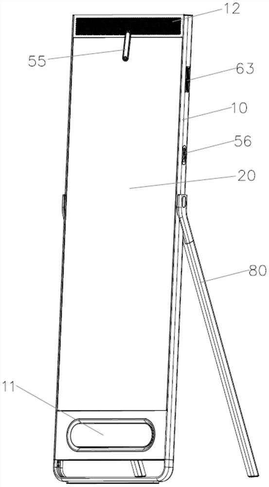
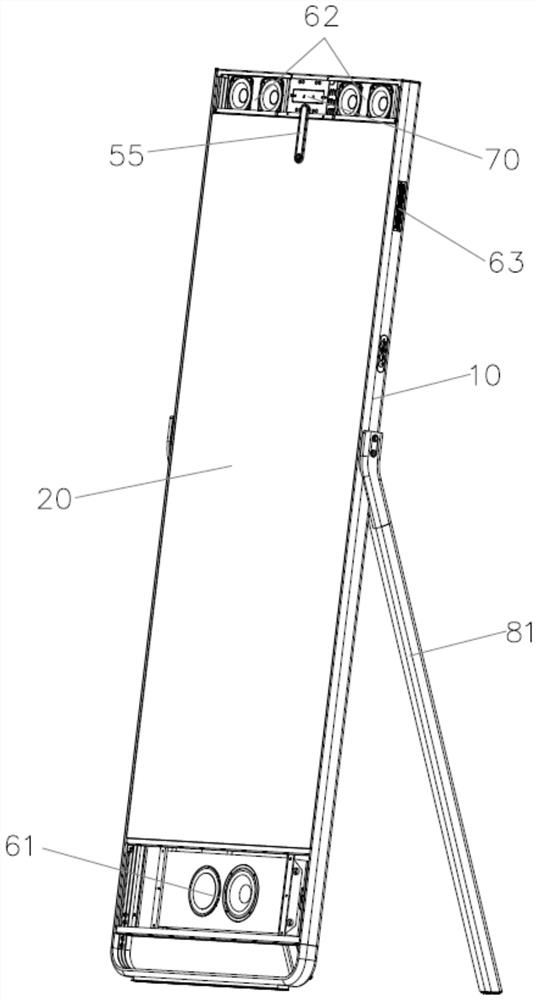
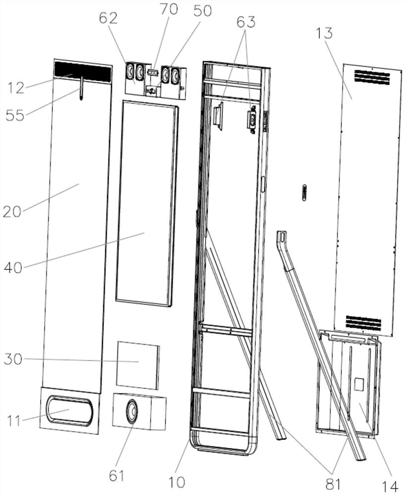
The invention relates to an intelligent mirror, and the intelligent mirror comprises a mounting frame, and mirror glass, a main control module, a display module, a camera mechanism and a sound box mechanism which are arranged on the mounting frame; the mirror glass is arranged on the front side of the mounting frame, and the main control module is electrically connected with the display module, the camera mechanism and the sound box mechanism; the display module is arranged on the back surface of the mirror glass and is used for displaying image content information; the camera mechanism is rotatably arranged at the upper end of the back surface of the mirror glass and is used for acquiring user image information and transmitting the user image information to the main control module; the sound box mechanism is used for outputting audio. According to the intelligent mirror, the shooting angle of the camera can be flexibly adjusted, and the output effect of the sound effect is improved.

Description

technical field [0001] The invention relates to the technical field of smart mirrors, in particular to a smart mirror. Background technique [0002] With the development of the economy and the improvement of living standards, smart mirrors can be seen everywhere in daily life, and users' demand for human-computer interaction is getting higher and higher. [0003] In the existing smart mirrors, the camera structure is generally directly fixed and installed on the back of the upper end of the mirror, and the user can take pictures or videos through the camera structure; however, the position of the camera is difficult to adjust, causing the user to be unable to match it during the shooting or video process. Best photography effects for users. In addition, in order to reduce wiring, the existing smart mirror integrates the structure of the speaker structure. In this way, although the arrangement of cables is reduced, the overall sound effect of the smart mirror is not good, wh...

Claims


Application Information

Patent Timeline
Patent Type & Authority Applications(China)
IPC IPC(8): H04N7/18H04N5/232G10L15/22H04R1/22A47G1/02
CPCH04N7/183G10L15/22H04R1/22A47G1/02G10L2015/223H04N23/695
Inventor 欧阳院红
Owner GUANGZHOU AIMYUNION NETWORK TECH
Learn More