Special arm wound surface dryer for burn department

A dryer and arm technology, which is applied in the field of special wound dryers for arms used in the burn department, can solve the problems of aggravating the infection of the affected area

Active Publication Date: 2021-08-27
奉节县人民医院
View PDF7 Cites 2 Cited by
  • Summary
  • Abstract
  • Description
  • Claims
  • Application Information

AI Technical Summary

Problems solved by technology

[0003] After taking the medicine, patients generally stay in a place with good air circulation, so that the affected area can be kept dry, which may aggravate the infection of the affected area

Method used


Image

  • Special arm wound surface dryer for burn department
  • Special arm wound surface dryer for burn department
  • Special arm wound surface dryer for burn department

Examples


Embodiment 1

[0034] A special wound desiccator for the arm of the burn department, such as Figure 1-3 As shown, it includes a first support frame 1, a second support frame 2, a limit ring 3, an outer frame 4, a sponge pad 5, a moving mechanism 6 and a drying mechanism 7. A first support frame 1, the first support frame 1 is equipped with a second support frame 2 in a rotating manner, the first support frame 1 is provided with a limit ring 3, and the outer frame 4 is provided with a sponge pad 5 on the front and rear sides, A moving mechanism 6 is arranged inside the outer frame 4 , and a drying mechanism 7 is arranged between the moving mechanism 6 and the outer frame 4 .

[0035] The user can use the desiccator on the injured wound of the patient. The user can pull the first support frame 1 and the second support frame 2 to support the outer frame 4. The limit ring 3 can rotate the second support frame 2. The angle is limited, and then the patient can place the injured arm under the out...

Embodiment 2

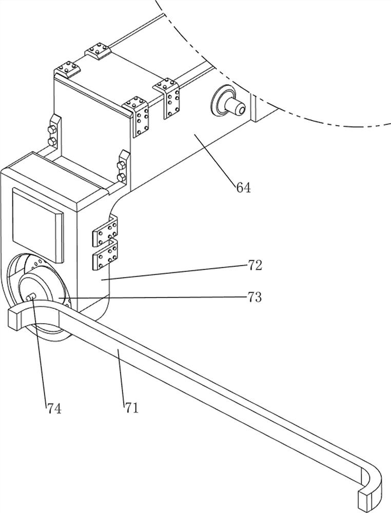
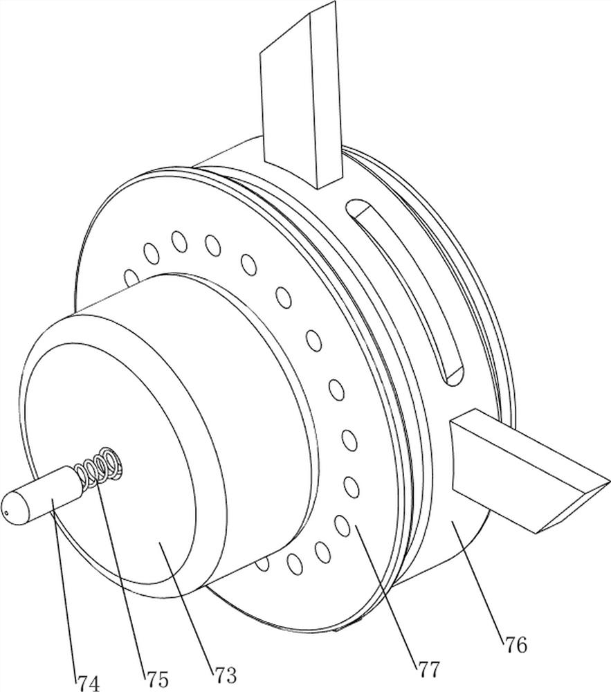
[0037] On the basis of Example 1, such as Figure 4-6As shown, the moving mechanism 6 includes a first handle 61, a first rotating shaft 62, a stay cord 63, a moving frame 64, a first slide bar 65, a sliding sleeve 66 and a first linear spring 67, and the front side of the outer frame 4 is rotated. There is a first rotating shaft 62, the right side of the first rotating shaft 62 is connected with a first handle 61, the inner side of the outer frame 4 is symmetrically provided with a first sliding rod 65, and the first sliding rod 65 on both sides is slidingly provided with a sliding sleeve 66 , a moving frame 64 is connected between the sliding sleeves 66 on both sides, the moving frame 64 is slidingly connected with the front side of the outer frame 4, a pull cord 63 is connected between the moving frame 64 and the first rotating shaft 62, and the moving frame 64 is connected to the outer frame 4 is connected with a first linear spring 67.

[0038] The user can turn the firs...

Embodiment 3

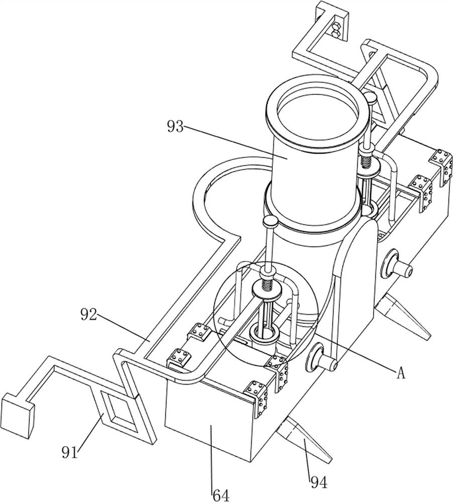
[0042] On the basis of Example 2, such as Figure 7-14 As shown, it also includes a disengagement mechanism 8, and the disengagement mechanism 8 includes a third fixed frame 81, a second motor 82, a first belt 83, a second rotating shaft 84, a first gear 85, a second gear 86, a first fixed column 87, block 88 and the 3rd linear spring 89, outer frame 4 left front side is provided with the 3rd fixed frame 81, the 3rd fixed frame 81 top is provided with the second motor 82, on the outer frame 4 close to the second motor 82 The position is provided with the first fixed column 87, and the second rotating shaft 84 is connected with the rotation type on the first fixed column 87, and the second rotating shaft 84 and the output shaft of the second motor 82 are all connected with pulleys, and the second rotating shaft is connected between the two pulleys. One belt 83, the second rotating shaft 84 right side rotation type is provided with the second gear 86, and the second rotating sha...


PUM


Abstract

The invention relates to a dryer, and particularly relates to a special arm wound surface dryer for a burn department. The invention provides the special arm wound surface dryer for the burn department, which can be used for drying a wound surface and disinfecting an affected part. The special arm wound surface dryer for the burn department comprises first supporting frames and an outer frame, and the first supporting frames are rotatably arranged on the two sides of the outer frame; second supporting frames are included and are rotatably arranged on the first supporting frames; limiting rings are included and are arranged on the first supporting frames; sponge cushions are included and arranged on the two sides of the outer frame; and a moving mechanism is included and is arranged on the inner side of the outer frame. According to the device, the effects that the wound surface can be dried, and the affected part can be disinfected are achieved; and the disinfectant is placed in the storage barrel and sprayed to the affected part through the mist spray head so that the affected part can be disinfected.

Description

technical field [0001] The invention relates to a drier, in particular to a drier for wounds specially used for arms in the department of burns. Background technique [0002] If a patient's arm is scalded or burned, medical personnel are required to apply medicine to the affected area. Since the affected area needs to be kept dry to a certain extent, it can prevent the affected area from deteriorating. [0003] After taking the medicine, the patient usually stays in a place with better air circulation, so that the affected area can be kept dry, which may aggravate the infection of the affected area. [0004] Therefore, when needing to design a kind of wound surface that can be dried, and can carry out disinfection to the affected part, the special wound surface desiccator of burn department arm. Contents of the invention [0005] In order to overcome the shortcomings of patients generally exposing the affected part of the wound to the air, which makes the affected part ag...

Claims


Application Information

Patent Timeline
Patent Type & Authority Applications(China)
IPC IPC(8): A47K10/48A61M35/00A61M11/00
CPCA47K10/48A61M35/20A61M11/00
Inventor 陈盛
Owner 奉节县人民医院
Why Eureka
Try Eureka