Visual nasal cavity cleaning instrument

A cleansing instrument and nasal cavity technology, which is applied in rhinoscope, medical science, bathing device, etc., can solve the problem that the cleansing instrument does not have a spraying device, and achieve the effect of relieving chronic rhinitis and preventing rhinitis

Inactive Publication Date: 2021-08-27
深圳市弘川科技有限公司
View PDF0 Cites 0 Cited by
  • Summary
  • Abstract
  • Description
  • Claims
  • Application Information

AI Technical Summary

Problems solved by technology

[0004] The traditional cleaning instrument does not have a spray device, and it is necessary to purchase an additional spray device to clean the nasal cavity

Method used


Image

  • Visual nasal cavity cleaning instrument
  • Visual nasal cavity cleaning instrument

Examples


Embodiment 1

[0027] Embodiment 1: the concrete structure of the present invention is as follows:

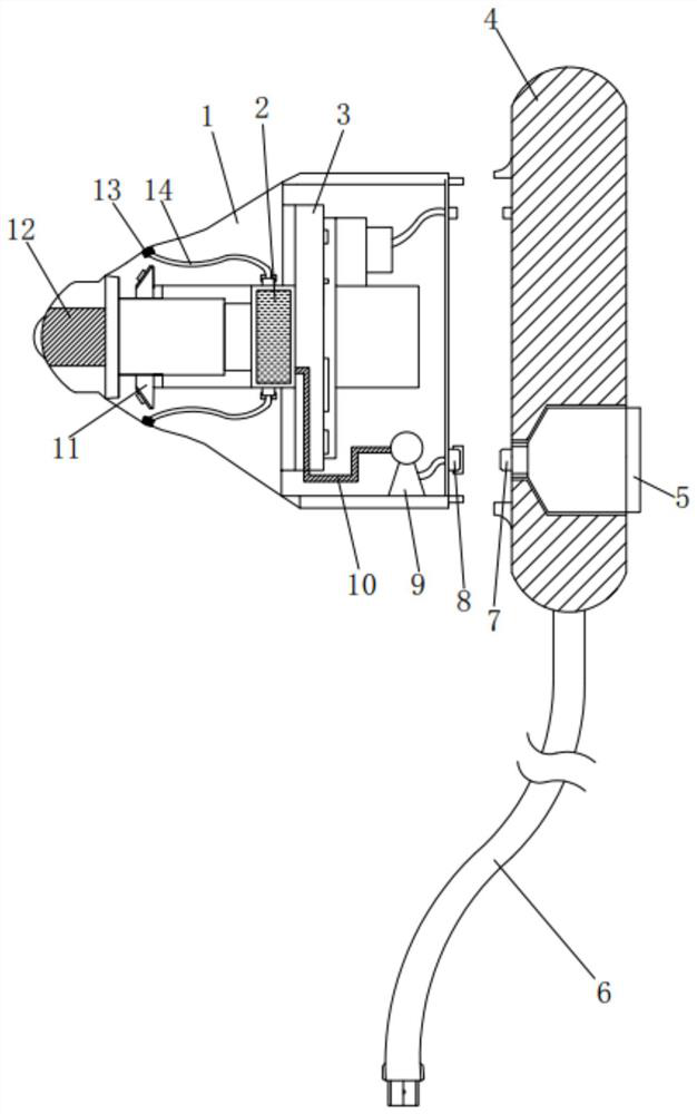
[0028] Please refer to the attached Figure 1-2 , a visual nasal cavity cleaning instrument of the present invention, comprising a shell portion 1, a light source portion 11 installed in the shell portion 1, an imaging portion 12 installed in the shell portion 1, and controlling the light source The PCB board 3 that the part 11 and the camera part 12 operate, the PCB board 3 is installed on a bracket arranged in the shell part 1, and the cleaning instrument also includes a spraying device installed in the shell part 1 , the spraying device includes:

[0029] Installed on the bracket and arranged on the liquid storage tank 2 facing away from the PCB board 3, and surrounding the side of the liquid storage tank 2, a number of first quick connectors distributed in a ring array are arranged;

[0030] A plurality of nozzles 13 installed on the shell 1 and distributed in a circular array, each noz...

Embodiment 2

[0041] The following is the operation of the visible nasal cavity cleaning instrument of the present invention:

[0042] Such as Figure 1-2 As shown, holding the handle part 4 of the present invention, the shell part 1 and the handle part 4 are fastened and fixed. At this time, the liquid storage tank 2, the hydraulic pump 9 and the container 5 form a connected structure through each conduit, wherein the container 5 and the container 5 There is an air intake channel between the hydraulic pumps 9 for air intake.

[0043] The shell part 1 and the handle part 4 also have an electrical access inter-plug interface, and the handle part 4 is connected to a power source through a power supply data line 6 or a rechargeable battery is installed inside the handle part 4 .

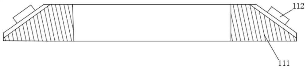
[0044] Physiological saline is housed in the container 5, and the cylindrical shell at the rear end of the shell part 1 has a certain length, and there are cylindrical shells for children and cylindrical shells for ...

Embodiment 3

[0048] The hydraulic pump 9 of the present invention can be installed in the handle portion 4 .

[0049] In summary, the nasal cavity cleaning instrument of the present invention can achieve deep cleaning without dead ends, can effectively prevent rhinitis, and relieve symptoms of chronic rhinitis.


PUM


Abstract

The invention discloses a visual nasal cavity cleaning instrument, which comprises a shell part, a light source part arranged in the shell part, a camera part arranged in the shell part and a PCB for controlling the light source part and the camera part to operate, wherein the PCB is installed on a support arranged in the shell part. The cleaning instrument further comprises a spraying device arranged in the shell part, the spraying device comprises a liquid storage tank, a spraying head and a hydraulic pump, and a plurality of first quick connectors distributed in a ring array mode are arranged around the side portion of the liquid storage tank. The spraying heads and the first quick connectors are connected one to one through a plurality of first guide pipes; the hydraulic pump is arranged in the rear cavity of the shell part, the liquid outlet end of the hydraulic pump is connected with the liquid storage tank through a second guide pipe, and the liquid inlet end of the hydraulic pump is connected with a second quick connector through a third guide pipe. By means of the nasal cavity cleaning instrument, dead-corner-free deep cleaning can be achieved, rhinitis can be effectively prevented, and symptoms of chronic rhinitis can be relieved.

Description

technical field [0001] The invention relates to a nasal cavity cleaning device, in particular to a visual nasal cavity cleaning instrument. Background technique [0002] With the improvement of living standards, people pay more and more attention to their own health problems (such as eyes and mouth, etc.). Compared with eyes and mouth, the ear canal and nasal cavity in the facial features are relatively easy to ignore. Many people never clean or check the ear canal and nasal cavity. When the long-term accumulated dirt or foreign objects in the ear canal / nasal cavity are not cleaned or discovered in time, discomfort or further inflammation will occur. [0003] Therefore, people need a cleaning instrument that can observe the situation in the nasal cavity voluntarily. [0004] The traditional cleaning instrument does not have a spray device, and it is necessary to purchase a spray device to clean the nasal cavity. Contents of the invention [0005] Aiming at the deficienci...

Claims


Application Information

Patent Timeline
IPC IPC(8): A61B1/233A61B1/04A61B1/06A61H35/04
CPCA61B1/04A61B1/0684A61B1/233A61H35/04A61H2205/023
Inventor 马浩力黄太亮
Owner 深圳市弘川科技有限公司
Why Eureka
Try Eureka