
Gear switching system for fitness equipment

A technology for gear switching and sports equipment, applied in the field of fitness equipment, can solve the problems of complicated operation and inconvenient use, and achieve the effects of internal stability, reliable structure and ingenious structure of the device

Active Publication Date: 2021-09-24
JIANGSU KANGFEITE POWER TECH
View PDF7 Cites 0 Cited by
  • Summary
  • Abstract
  • Description
  • Claims
  • Application Information

AI Technical Summary

Problems solved by technology

[0002] Fitness equipment is widely loved by the masses of the people, and it is very helpful for physical fitness. Due to the wide audience of fitness equipment, it is necessary to set gear switching devices in the equipment to meet the different needs of different groups of people. Traditional fitness exercises The strength adjustment of the equipment is generally realized by manually adding and subtracting weight components, and the operation is complicated. The prior art (CN202021344438.9) relates to an adjustable dumbbell gear adjustment device, including a handle, a dial and a bell plate. The handle is The combination of the central shaft and the handle cover, the two ends of the central shaft are provided with circlip grooves and gear steps from the outside to the inside, the central shaft is also connected to the index plate and the bell box, the index plate is There is a lock plate positioning slot and a steel ball gear hole, and the bell plate box is also connected with a bell plate box cover, and the bell plate box cover is connected with a steel ball gear hole and a lock plate positioning groove. The adjustment device still needs to be manually adjusted. Operation brings inconvenience to use, therefore, the present invention provides a gear switching system for fitness equipment, which can automatically realize the adjustment of gears, which is convenient and fast, and has a high degree of automation

Method used


Image

  • Gear switching system for fitness equipment
  • Gear switching system for fitness equipment
  • Gear switching system for fitness equipment

Examples


Embodiment

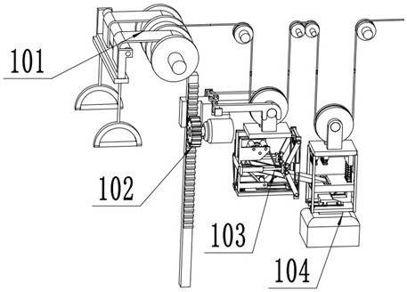
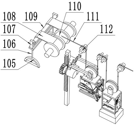
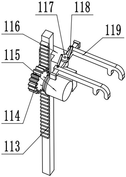
[0020] Example: such as figure 1 , figure 2 The gear shifting system of a kind of fitness equipment shown, comprises pulling device 101, lifting device 102, first counterweight assembly 103, second counterweight assembly 104, pulling device 101, lifting device 102, first counterweight assembly 103. The second counterweight assembly 104 is located inside the housing of a gear switching system of a kind of fitness equipment, wherein the pulling device 101 includes a pull ring 105, and the pull ring 105 is arranged on the outside of the housing, and the pull ring 105 is installed through a pull rope 106 On the tape 108, the tape 108 goes around the shaft 109, the shaft 109 is rotatably mounted on the pull bracket 107, the pull bracket 107 is fixedly mounted on the shell, the tape 108 is wound on the reel 110, and the reel 110 is rotatably mounted on the shell, The rope 111 is wound on the reel 110, the winding direction of the tape 108 is opposite to that of the rope 111, the r...


PUM


Abstract

The invention discloses a gear switching system of fitness equipment, which belongs to the technical field of fitness equipment and comprises a pulling device, a lifting device, a first counterweight assembly, a second counterweight assembly, a pulling device, a lifting device, and a first counterweight The parts and the second counterweight assembly are all located inside the casing of a gear switching system of fitness equipment, wherein the pulling device includes a pull ring, which is arranged outside the casing, and the pull ring is installed on the tape through the pull rope. The belt winds around the rotating shaft, the winding direction of the winding belt is opposite to that of the rope, the rope is wound on a plurality of fixed wheels, and the fixed wheels are rotatably mounted on the casing, and the first counterweight assembly and the second counterweight assembly are respectively arranged on the rope through the fixed wheels For the part between the two fixed wheels, the lifting device is installed on the shell to realize the lifting control of the first counterweight assembly. The present invention realizes the control and adjustment of the pulling force through the pulley mechanism, with ingenious structure and high degree of automation.

Description

technical field [0001] The invention relates to the technical field of fitness equipment, in particular to a gear switching system of fitness equipment. Background technique [0002] Fitness equipment is widely loved by the masses of the people, and it is very helpful for physical fitness. Due to the wide audience of fitness equipment, it is necessary to set gear switching devices in the equipment to meet the different needs of different groups of people. Traditional fitness exercises The strength adjustment of the equipment is generally realized by manually adding and subtracting weight components, and the operation is complicated. The prior art (CN202021344438.9) relates to an adjustable dumbbell gear adjustment device, including a handle, a dial and a bell plate. The handle is The combination of the central shaft and the handle cover, the two ends of the central shaft are provided with circlip grooves and gear steps from the outside to the inside, the central shaft is als...

Claims


Application Information

Patent Timeline
Patent Type & Authority Patents(China)
IPC IPC(8): A63B21/062
CPCA63B21/154A63B21/0632
Inventor 蒋建华
Owner JIANGSU KANGFEITE POWER TECH
Learn More