Bridge shock-absorption and vibration-proof support
A technology of anti-seismic bearings and bridges, which is applied in the field of bridge shock absorption, can solve the problems of bridge shock absorption, failure to meet the use requirements, poor shock absorption effect, etc., to eliminate lateral vibration, offset lateral vibration, and achieve good vibration reduction effect of effect
- Summary
- Abstract
- Description
- Claims
- Application Information
AI Technical Summary
Problems solved by technology
Method used
Image
Examples
Embodiment 1
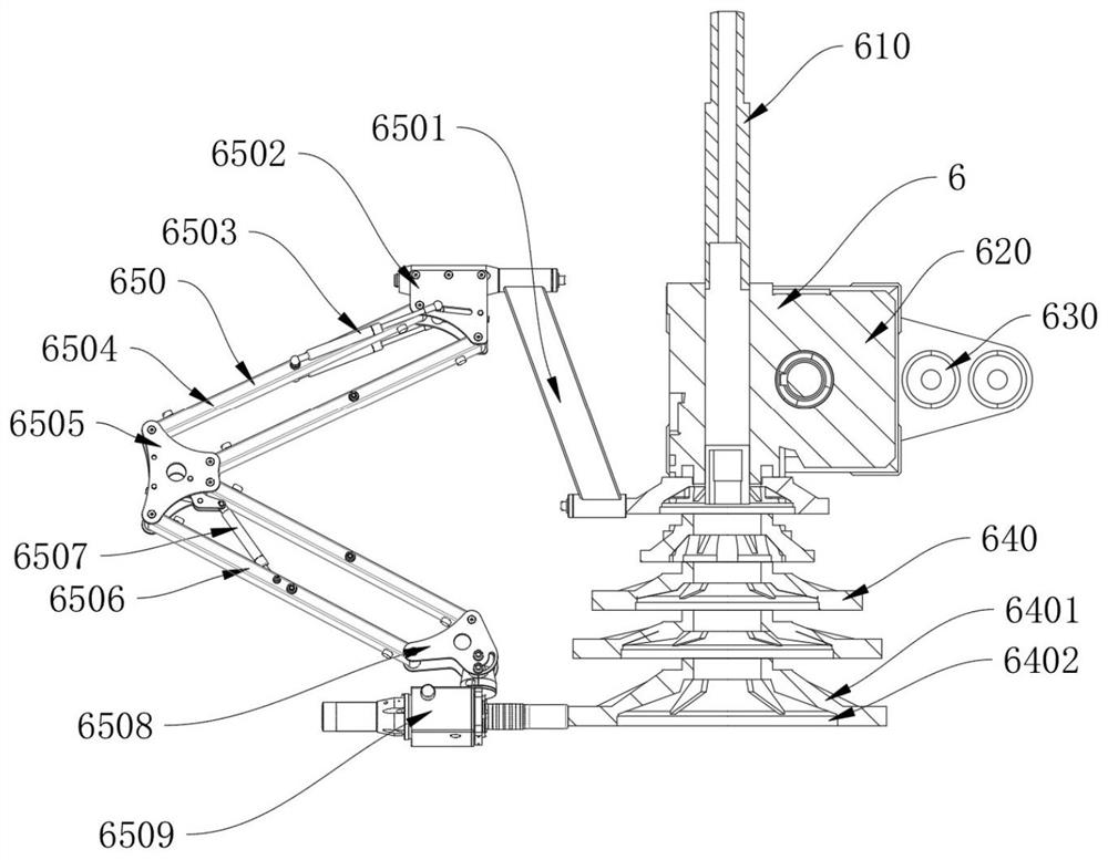
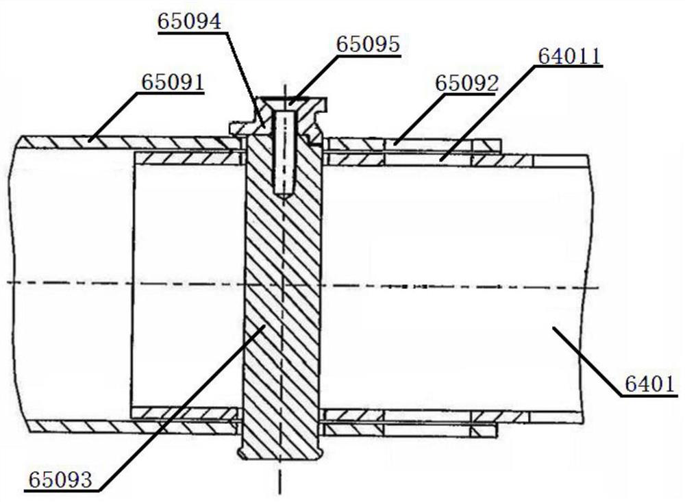
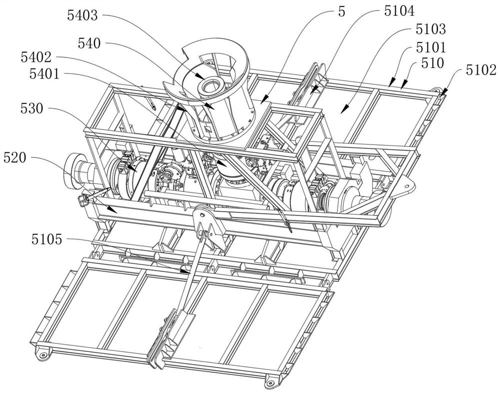
[0053] Such as Figure 1-6 As shown, a bridge shock-absorbing anti-seismic bearing of the present invention includes a spout assembly 6, and the spout assembly 6 includes a spout nozzle 610, a spout mounting part 620, an adjustable support 630 and a movable spout mechanism 640, and the spout nozzle 610 is located on the top of the spout mounting part 620, the spout mounting part 620 is fixedly connected with the ejection nozzle 610, the adjustable support 630 is located at the side of the spout mounting part 620, the spout mounting part 620 is fixedly connected with the adjustable support 630, and the movable The spout mechanism 640 is located at the bottom of the spout mounting part 620, and the movable spout mechanism 640 is movably connected with the spout mounting part 620. The side of the movable spout mechanism 640 is provided with a movable arm mechanism 650, and the movable arm mechanism 650 is connected with the upper and lower ends of the movable spout mechanism 640. ...
Embodiment 2
[0059] Such as Figure 1-6 As shown, a bridge shock-absorbing anti-seismic bearing of the present invention includes a spout assembly 6, and the spout assembly 6 includes a spout nozzle 610, a spout mounting part 620, an adjustable support 630 and a movable spout mechanism 640, and the spout nozzle 610 is located on the top of the spout mounting part 620, the spout mounting part 620 is fixedly connected with the ejection nozzle 610, the adjustable support 630 is located at the side of the spout mounting part 620, the spout mounting part 620 is fixedly connected with the adjustable support 630, and the movable The spout mechanism 640 is located at the bottom of the spout mounting part 620, and the movable spout mechanism 640 is movably connected with the spout mounting part 620. The side of the movable spout mechanism 640 is provided with a movable arm mechanism 650, and the movable arm mechanism 650 is connected with the upper and lower ends of the movable spout mechanism 640. ...
Embodiment 3
[0069] Such as Figure 1-6 As shown, a bridge shock-absorbing anti-seismic bearing of the present invention includes a spout assembly 6, and the spout assembly 6 includes a spout nozzle 610, a spout mounting part 620, an adjustable support 630 and a movable spout mechanism 640, and the spout nozzle 610 is located on the top of the spout mounting part 620, the spout mounting part 620 is fixedly connected with the ejection nozzle 610, the adjustable support 630 is located at the side of the spout mounting part 620, the spout mounting part 620 is fixedly connected with the adjustable support 630, and the movable The spout mechanism 640 is located at the bottom of the spout mounting part 620, and the movable spout mechanism 640 is movably connected with the spout mounting part 620. The side of the movable spout mechanism 640 is provided with a movable arm mechanism 650, and the movable arm mechanism 650 is connected with the upper and lower ends of the movable spout mechanism 640. ...
PUM
 Abstract
Description
Claims
Application Information
 - R&D Engineer
- R&D Manager
- IP Professional
- Industry Leading Data Capabilities
- Powerful AI technology
- Patent DNA Extraction
Browse by: Latest US Patents, China's latest patents, Technical Efficacy Thesaurus, Application Domain, Technology Topic, Popular Technical Reports.
© 2024 PatSnap. All rights reserved.Legal|Privacy policy|Modern Slavery Act Transparency Statement|Sitemap|About US| Contact US: help@patsnap.com


