Flood control wall for water conservancy projects

A water conservancy project and wall technology, applied in water conservancy projects, sea area projects, embankments, etc., can solve the problems of poor flood control effect, difficult disassembly and assembly, etc., so as to achieve not easy bending and deformation, increased impact resistance, and good flood control effect Effect

Inactive Publication Date: 2021-08-27
王磊
View PDF2 Cites 0 Cited by
  • Summary
  • Abstract
  • Description
  • Claims
  • Application Information

AI Technical Summary

Problems solved by technology

[0006] The present invention is committed to developing a water conservancy project flood control wall, which solves the problems of poor flood control effect and difficult disassembly and assembly

Method used


Image

  • Flood control wall for water conservancy projects
  • Flood control wall for water conservancy projects
  • Flood control wall for water conservancy projects

Examples


Embodiment 1

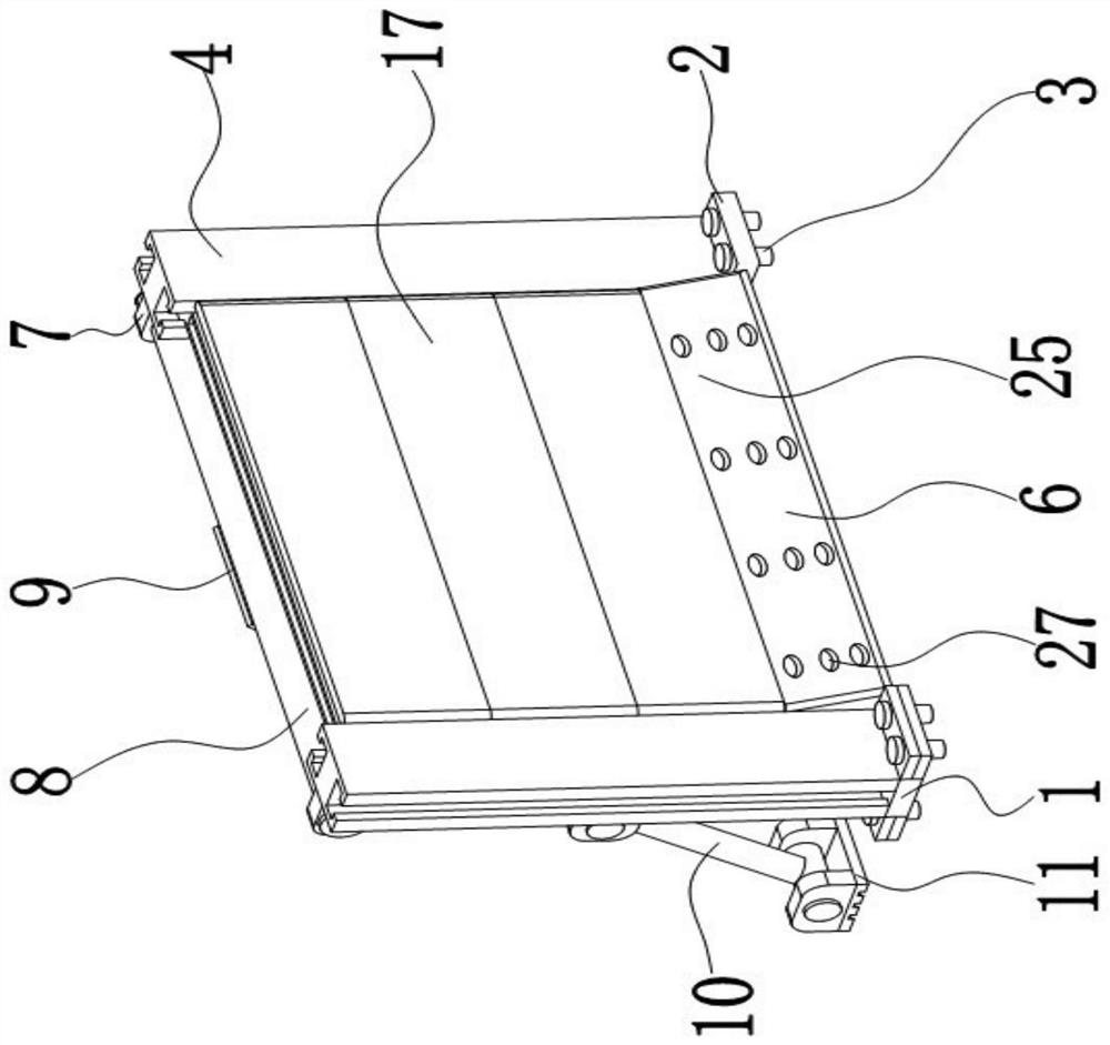
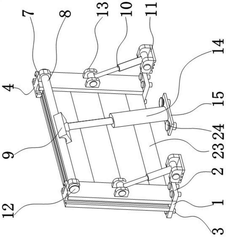
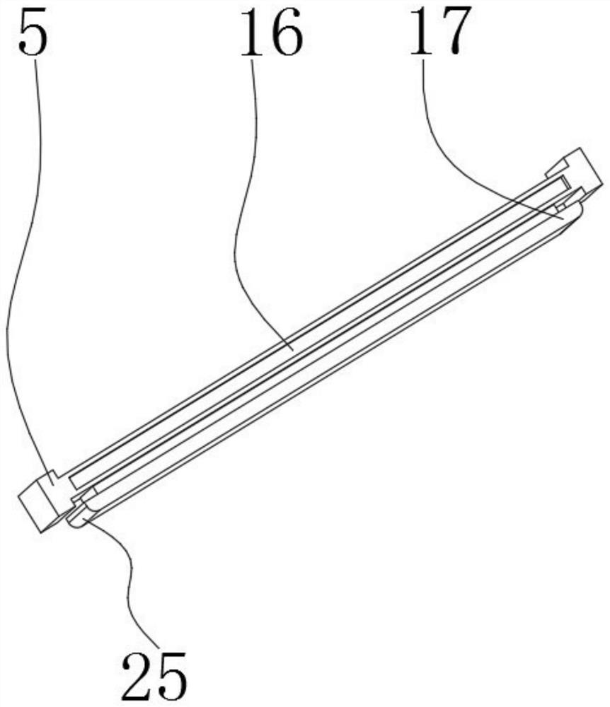
[0032] Such as Figure 1 to Figure 7 As shown, the present invention provides a flood control wall for water conservancy projects, including a base 1, a support frame 4 is sealed and rotated on the base 1, and a baffle 5 is movably connected to the inner side of the support frame 4, and the middle part of the top of the baffle 5 is opened. There is an inlay groove 16, a rectangular block 18 is fixedly installed in the middle of the right side of the baffle plate 5, a spring 19 is fixedly installed inside the rectangular block 18, a top plate 21 is fixedly connected to the right side of the spring 19, and a buffer is fixedly connected to the right side of the top plate 21 Plate 17, the left side of buffer plate 17 is provided with chute opening 20, and buffer plate 17 is sealed and slidably connected with rectangular block 18 through chute opening 20, and the bottom of baffle plate 5 is fixedly installed with mosaic block 22, and the bottom of mosaic block 22 is sealed It is mo...

Embodiment 2

[0041] Because floods are often accompanied by relatively large waves, if the waves of the flood directly impact the device repeatedly and repeatedly, it may cause the No. 1 fixing nail 3 and the No. 2 fixing nail 24 of the device to loosen or deform and damage other parts, resulting in This device loses the flood protection effect. Therefore, the device has been further improved.

[0042] Such as Figure 7-8 As shown, the support frame 4 is sealed and rotated on the base 1, the sealing part 6 is provided with a second pipeline 27, the buffer plate 17, the rectangular block 18 and the baffle plate 5 form a second cavity 602, and the second pipeline 27 makes the first The second cavity 602 communicates with the outside of the device to guide a part of the flood into the second cavity 602 through the second pipeline 27; The outlet is connected with the second pipeline 27, and the outlet is provided with a filter screen, which can filter debris in the flood to prevent the secon...

Embodiment 3

[0046] After the flood recedes, when the device is recycled, because the flood contains a lot of silt and fine debris after being filtered by the filter screen on the outlet, the silt and fine debris etc. gather in the second cavity 602, if not Cleaning up in time will cause the spring 19 to be rusted and damaged; excessively small foreign matter blocked in the second cavity 602 will cause the spring 19 to be unable to be compressed, so before recycling the device, it is necessary to clean the mud in the second cavity 602. Clean up sand, debris, etc.

[0047] Such as Figure 7-8 As shown, a first cavity 601 is provided in the sealing portion 6, and the first cavity 601 communicates with the second cavity 602 formed by the buffer plate 17, the rectangular block 18 and the baffle plate 5 through the first pipeline 26; the first pipeline 26 is provided with a one-way valve 28; the outer end of the second pipeline 27 is provided with a sealing plug.

[0048]A first cavity 601 is...


PUM


Abstract

The invention belongs to the technical field of water conservancy projects, and discloses a flood control wall for water conservancy projects, which comprises a base and a supporting frame, a baffle is movably connected to the inner side of the supporting frame, a rectangular block is fixedly installed in the middle of the right side of the baffle, a spring is fixedly installed in the rectangular block, a top plate is fixedly connected to the right side of the spring, and the right side of the top plate is fixedly connected with a buffer plate. Under the guidance of a slope for flood waves, the buffer plate, the spring, a support plate, a No.1 ejector rod and a No.2 ejector rod effectively buffer the impact of a part of flood; and under the guidance of a second pipeline on the slope, the other part of the flood enters a second cavity and impacts the inner side of the buffer plate, meanwhile, the flood acting on the inner side of the buffer plate and the flood acting on the outer side of the buffer plate can be counteracted, then the flood is divided into two parts, the impact force of the flood to the flood is counteracted, and the floor control wall has a better buffering effect.

Description

technical field [0001] The invention belongs to the technical field of water conservancy engineering, in particular to a flood control wall of a water conservancy project. Background technique [0002] A kind of concrete or masonry water retaining structure used to ensure the flood control safety of towns and important industrial and mining enterprises, along rivers, coastal areas (partial seawalls) or other special requirements, also known as flood control walls. The function of flood control walls is the same as that of dikes. There are traffic arteries along the river in the city, and the buildings are dense. Sometimes due to the limitations of the built projects, or the needs of urban planning and development, or the limitation of soil sources, flood walls have to be used to reduce land occupation and demolition. [0003] Most of the traditional flood control methods use sandbags to pile up into a wall to block the flood. The whole process needs to be manually carried an...

Claims


Application Information

Patent Timeline
Patent Type & Authority Applications(China)
IPC IPC(8): E02B3/10E02B3/16B08B9/093
CPCB08B9/093E02B3/10E02B3/106E02B3/16Y02A10/11
Inventor 王磊杨小康
Owner 王磊
Why Eureka
Try Eureka