Check patentability & draft patents in minutes with Patsnap Eureka AI!

Rotary knob rotation detection method and rotary knob assembly

A technology of rotation detection and knob, applied in measuring devices, control components, instruments, etc., can solve the problems of low reliability, susceptibility to electromagnetic interference, and high cost of magnetic angle sensors, and achieve the effect of preventing electromagnetic interference and improving reliability.

Pending Publication Date: 2021-08-27
HANGZHOU ROBAM APPLIANCES CO LTD
View PDF0 Cites 0 Cited by
  • Summary
  • Abstract
  • Description
  • Claims
  • Application Information

AI Technical Summary

Problems solved by technology

[0005] The object of the present invention is to provide a rotation detection method of a knob and a knob assembly, so as to alleviate the problems existing in the prior art, such as magnetic knobs and other knobs, which usually use a magnetically sensitive angle sensor installed inside to detect the rotation angle, but the magnetically sensitive angle The sensor has high cost, is susceptible to electromagnetic interference, and has low reliability technical problems

Method used


Image

  • Rotary knob rotation detection method and rotary knob assembly
  • Rotary knob rotation detection method and rotary knob assembly
  • Rotary knob rotation detection method and rotary knob assembly

Examples


Embodiment 1

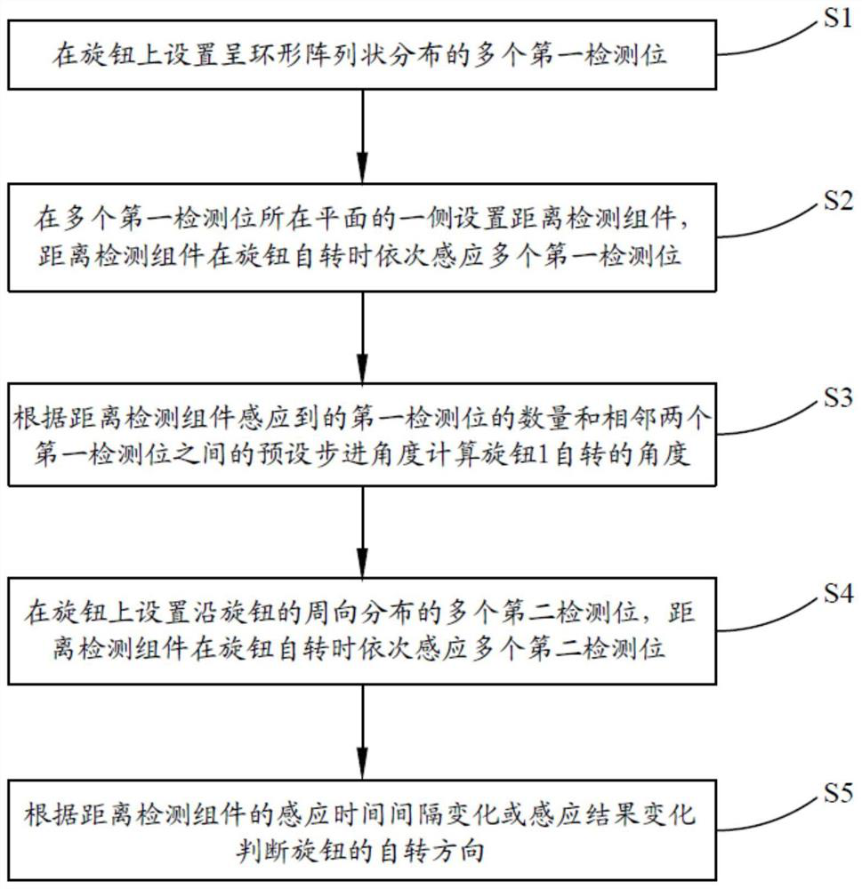
[0056] Such as figure 1 As shown, the rotation detection method of the knob provided in this embodiment includes:

[0057] Step S1: setting a plurality of first detection bits 10 distributed in a circular array on the knob 1;

[0058] Step S2: Install a distance detection component 2 on one side of the plane where the multiple first detection positions 10 are located, and the distance detection component 2 senses the multiple first detection positions 10 sequentially when the knob 1 rotates;

[0059] Step S3: Calculate the rotation angle of the knob 1 according to the number of the first detection positions 10 sensed by the distance detection component 2 and the preset step angle between two adjacent first detection positions 10 .

[0060] Wherein, since the plurality of first detection positions 10 are distributed in a circular array, the included angle between two adjacent first detection positions 10 in each group is equal, and the included angle is a preset step angle. W...

Embodiment 2

[0095] Such as Figure 7 As shown, the knob assembly provided in this embodiment includes a knob 1 and a distance detection assembly 2 . The knob 1 is provided with a plurality of first detection bits 10 distributed in a circular array. The distance detection component 2 is arranged at intervals on one side of the plane where the plurality of first detection positions 10 are located, and is used to sequentially sense the plurality of first detection positions 10 during the rotation of the knob 1 to calculate the angle after the rotation of the knob 1 .

[0096] After the knob 1 in the knob assembly rotates, the distance detection assembly 2 can sense a plurality of first detection positions 10 in sequence. Since a plurality of first detection positions 10 are distributed in a circular array, the angles between two adjacent first detection positions 10 in each group are equal, and the angle is a preset known value. The detected number of digit 10, combined with the above incl...


PUM


Abstract

The invention provides a rotary knob rotation detection method and a rotary knob assembly, and relates to the technical field of control switches. The detection method comprises the following steps: a plurality of first detection positions which are distributed in an annular array shape are arranged on a rotary knob; a distance detection assembly is arranged on one side of the plane where the multiple first detection positions are located, and the distance detection assembly senses the multiple first detection positions in sequence when the rotary knob rotates; and the rotation angle of the rotary knob is calculated according to the number of the first detection positions sensed by the distance detection assembly and a preset stepping angle between every two adjacent first detection positions. According to the detection method provided by the invention, the distance detection assembly and the first detection positions are matched with each other to detect the rotation angle of the rotary knob, and a magnetic sensitive angle sensor does not need to be used.

Description

technical field [0001] The invention relates to the technical field of control switches, in particular to a rotation detection method of a knob and a knob assembly. Background technique [0002] At present, the control switches of most electrical appliances are mechanical buttons or touch buttons. The disadvantages of this kind of control switches are poor tactility and poor feedback experience, but the knob can solve the above problems very well. The knob has a clear touch and strong feedback. [0003] The magnetic knob is a kind of knob that is connected to the electrical panel by means of magnetic attraction. Because of its unique shape and good user experience, the magnetic knob is widely used. When using a magnetic knob, it is often necessary to detect its rotation angle to control related components in electrical appliances to perform related functions. Existing magnetic knobs usually use a magnetically sensitive angle sensor installed inside to detect the rotation an...

Claims


Application Information

Patent Timeline
Patent Type & Authority Applications(China)
IPC IPC(8): G01B21/22G05G1/10
CPCG01B21/22G05G1/10
Inventor 任富佳丁涛朱世民郁明跃周海昕
Owner HANGZHOU ROBAM APPLIANCES CO LTD
Features
  • R&D
  • Intellectual Property
  • Life Sciences
  • Materials
  • Tech Scout
  • Unparalleled Data Quality
  • Higher Quality Content
  • 60% Fewer Hallucinations
Learn More