Balloon catheter, delivery system and stent system
A balloon catheter and delivery system technology, applied in the field of medical devices, can solve the problems of easy thrombosis, non-adjustment, and vascular structure adjustment.
- Summary
- Abstract
- Description
- Claims
- Application Information
AI Technical Summary
Problems solved by technology
Method used
Image
Examples
Embodiment 1
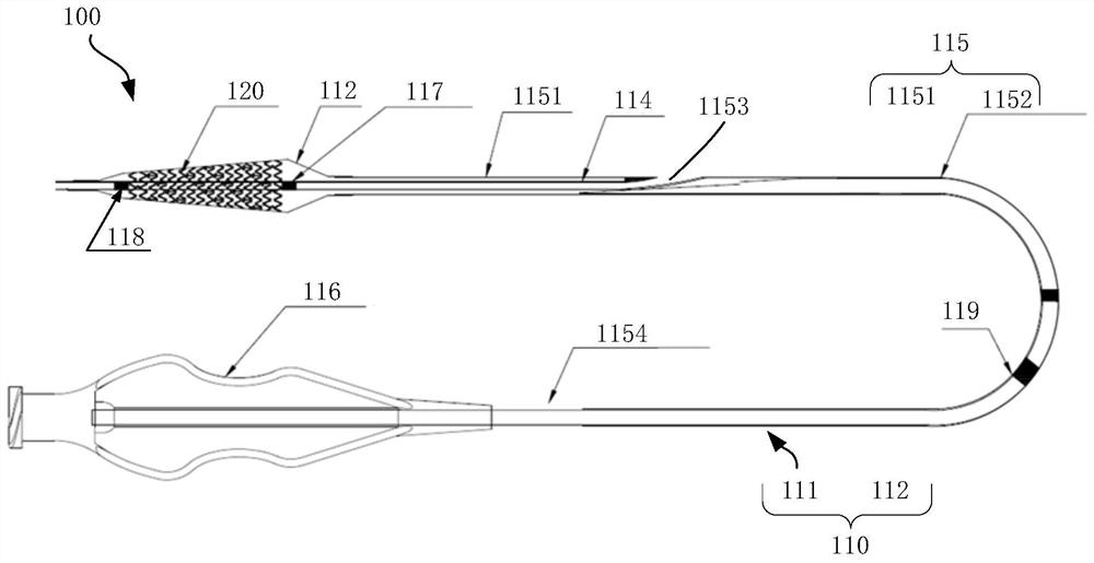
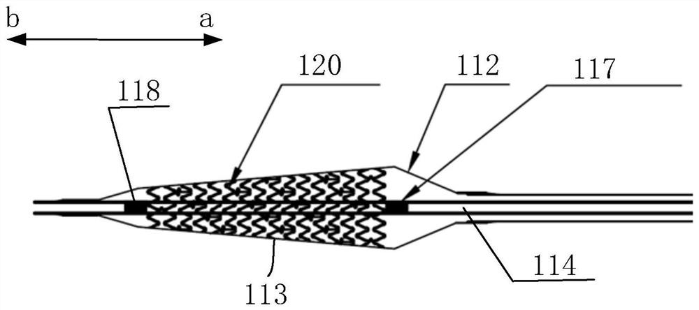
[0040] figure 1 Schematic diagram of the structure of the stent system provided for the preferred embodiment of the present invention, figure 2 yes figure 1 A partial schematic view of the distal end of the stent system shown. Such as Figure 1~2 As shown, the present embodiment provides a stent system 100, including a balloon catheter 110 and a stent 120, the balloon catheter 110 includes a catheter body 111 and a balloon 112; the balloon 112 is arranged at the distal end of the catheter body 111, and is used for loading The stent 120 ; the stent 120 is used to be pressed and held on the balloon 112 , and then the expansion of the stent 120 is realized by filling and expanding the balloon 112 . The expanded balloon 112 can be a straight balloon (ie, the expanded shape is cylindrical), or a conical balloon (ie, the expanded shape is truncated conical or nearly conical). Straight balloons can match blood vessels with uniform inner diameter; tapered balloons can better matc...
Embodiment 2
[0053] image 3 Schematic diagram of the structure of the stent system provided by the second preferred embodiment of the present invention, Figure 4 yes image 3 A partial schematic view of the distal end of the stent system shown. The structure of the stent system provided in this embodiment is basically the same as that of the stent system in Embodiment 1, and only the differences will be described below.
[0054] Such as Figure 3-4As shown, this embodiment provides a balloon catheter 110', including a catheter body 111 and a balloon 112', wherein the expanded balloon 112' is also a tapered balloon. The difference from the balloon 112 in Embodiment 1 is that the expanded balloon 112' includes two conical sections connected in succession in the axial direction, namely the first conical section 1131 and the second conical section 1132. The diameters of each tapered segment gradually increase from the distal end to the proximal end. The diameter of the wide end of the f...
Embodiment 3
[0060] Figure 5 It is an enlarged view of the distal end of the balloon catheter provided by the third preferred embodiment of the present invention. The structure of the balloon catheter 110 ″ provided in this embodiment is basically the same as that of the balloon catheter 110 in Embodiment 1, and only the differences will be described below.
[0061] Such as Figure 5 As shown, the balloon catheter 110" of this embodiment includes a catheter body 111 and a balloon 112" located at the distal end of the catheter body 111. The balloon 112" includes an inner balloon 112a and an outer balloon 112b. An inner balloon 112a is nested, and the outer balloon 112b and the inner balloon 112a are inflated and expanded respectively to form different stent configurations, thereby adapting to different vascular structures. Wherein, the inner balloon 112a can adopt the ball in the first embodiment The balloon 112 or the balloon 112' in the second embodiment are not further described here....
PUM
| Property | Measurement | Unit |
|---|---|---|
| Hardness | aaaaa | aaaaa |
Abstract
Description
Claims
Application Information
 - R&D
- Intellectual Property
- Life Sciences
- Materials
- Tech Scout
- Unparalleled Data Quality
- Higher Quality Content
- 60% Fewer Hallucinations
Browse by: Latest US Patents, China's latest patents, Technical Efficacy Thesaurus, Application Domain, Technology Topic, Popular Technical Reports.
© 2025 PatSnap. All rights reserved.Legal|Privacy policy|Modern Slavery Act Transparency Statement|Sitemap|About US| Contact US: help@patsnap.com


