Multi-blade rotary feeding pipe cutting cutterhead and pipe cutter

A technology of pipe cutter and cutter head, which is applied in the direction of pipe shearing device, shearing device, shearing machine equipment, etc., can solve the problems of low operation efficiency, difficulty in multiple blades, wrist damage, etc., and achieve the effect of convenient operation.

Pending Publication Date: 2021-08-31
邱强生
View PDF0 Cites 2 Cited by
  • Summary
  • Abstract
  • Description
  • Claims
  • Application Information

AI Technical Summary

Problems solved by technology

Existing pipe cutters are generally driven by hand, so that the pipe cutter rotates around the pipe to achieve cutting. This kind of pipe cutter cannot be used in some relatively narrow occasions, and the work efficiency is low. Operators use it for a long time. Easy to cause damage to the wrist
In addition, although there are some electric pipe cutters at present, there are usually the following problems: ①There is only one blade, and if multiple blades are used, it is difficult to feed multiple blades synchronously; ②It is difficult to synchronize the blade feeding process and the cutterhead rotation process ; ③ It is difficult to make the cutting blade perform uniform and small step-by-step feeding with the rotation of the cutter head; the above problems will also lead to problems such as low cutting efficiency and poor quality of pipe cutting
In addition, the existing pipe cutters generally have the problem that the position of the pipe is difficult to fix during the pipe cutting process, which leads to misalignment of the cutting position due to the accidental sliding of the pipe relative to the cutter head during pipe cutting, which affects the quality of pipe cutting

Method used


Image

  • Multi-blade rotary feeding pipe cutting cutterhead and pipe cutter
  • Multi-blade rotary feeding pipe cutting cutterhead and pipe cutter
  • Multi-blade rotary feeding pipe cutting cutterhead and pipe cutter

Examples


Embodiment 1

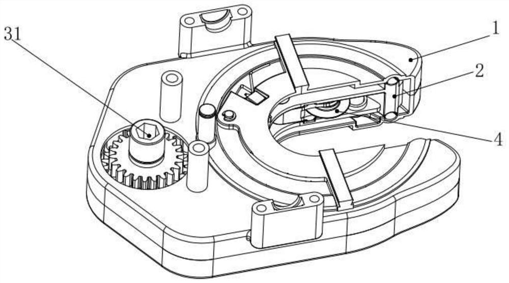
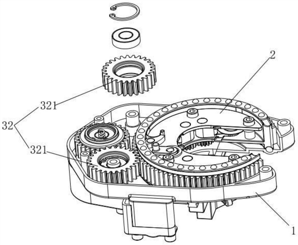
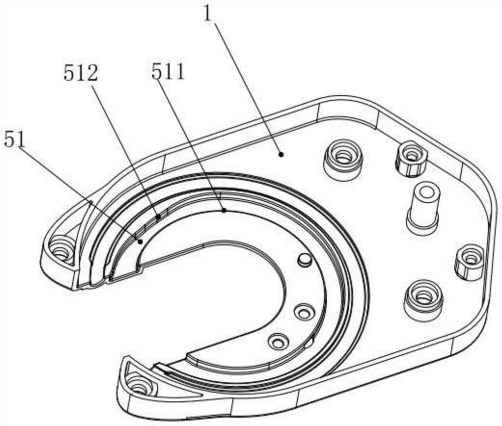
[0059] Such as Figure 1-10 As shown, the multi-blade rotary feed pipe cutting cutterhead 10 includes a housing 1 and also includes:

[0060]The cutter head 2 is installed in the casing 1 through the ball bearing positioning structure 21 arranged on both ends of the cutter head 2 and can rotate around its axis. Both the casing 1 and the cutter head 2 are provided with The through hole in the center forms a cutting space for placing the cutting object (pipe) in the through hole; the cutter head 2 is a ring-shaped structure (ie a C-like structure) with an opening, and the housing 1 is also provided with a corresponding The opening, the opening of the cutter head 2 and the opening of the casing 1 communicate with the cutting space. The effect of setting the opening on the cutter head 2 and the housing 1 is to facilitate the pipe cutting cutter head 2 to be directly placed on the pipe at any position of the pipe to be cut for cutting, which is convenient for use.

[0061] The cu...

Embodiment 2

[0072] On the basis of embodiment 1 technical scheme, make following improvement:

[0073] Such as Figure 11-15As shown, the cutter head 2 is installed in the casing 1 through a ball positioning structure arranged on the outer ring of the cutter head 2 . The quantity of described knife rest is three, is respectively knife rest a41, knife rest b42 and knife rest c43, is arc-shaped structure and the outer side is provided with rack, the side of each knife rest and described cutter head 2 respectively Matching arc-shaped guide protrusions and arc-shaped guide grooves are provided, and the tool post linkage 53 also includes a reverse linkage rack 532, and the feed gear 522 is connected to the reverse direction through a driven feed gear 5221. Linkage rack 532, thereby make reverse linkage rack 532 and described forward linkage rack 531 movement directions opposite, one end of knife rest is equipped with described blade 4, wherein the rack of knife rest a41 and knife rest b42 are...

Embodiment 3

[0076] On the basis of embodiment 1 technical scheme, make following improvement:

[0077] Such as Figure 16 As shown, the number of the tool holders is three, which are respectively the tool holder a41, the tool holder b42 and the tool holder c43. One end of the tool holder a41 is hinged on the cutter head 2 and is provided with the cutter bar gear a4111, and the other end The blade 4 is installed, one end of the knife rest b42 is hinged on the cutter head 2 and is provided with the cutter bar gear b4211, the other end is equipped with the blade 4, and one end of the knife rest c43 is hinged on the cutter head 2 There is also a cutter bar gear c4311, and the blade 4 is installed at the other end, wherein the cutter bar gear a4111 and the cutter bar gear b4211 are both meshed with the forward linkage rack 531, and the cutter bar gear c4311 is meshed with the cutter bar gear a4111. This design makes when the knife rest linkage 53 rotates in the forward direction, it will driv...


PUM


Abstract

The invention relates to the technical field of cutting tools, in particular to a multi-blade rotary feeding pipe cutting cutterhead and a pipe cutter. The multi-blade rotary feeding pipe cutting cutterhead comprises a shell, a cutterhead body, a cutterhead driving device used for driving the cutterhead body to rotate in the shell, a plurality of cutter rests and blades arranged on the cutterhead body, and a blade feeding mechanism used for driving the blades to rotate along with the cutterhead body in the forward direction to conduct synchronous stepping feeding. The cutterhead has the advantages that the multiple blades are arranged, the multiple blades can be driven to be synchronously fed in an electric driving mode, the blade feeding process and the cutterhead rotating process are synchronously carried out, and each blade can synchronously carry out tiny stepping type feeding every time the cutterhead rotates by a circle. The pipe cutter comprises the multi-blade rotary feeding pipe cutting cutterhead and a clamping device which are coaxially and fixedly connected together. The pipe cutter has the advantage that it can be guaranteed that pipes cannot accidentally slide relative to the cutterhead in the pipe cutting process.

Description

technical field [0001] The invention relates to the technical field of cutting tools, in particular to a multi-blade rotary feed pipe cutting cutter head and a pipe cutter. Background technique [0002] The pipe cutter is mainly a cutting tool for stainless steel pipes, copper pipes, and plastic pipes. It generally includes a cutter head and a cutting blade arranged on the cutter head. When working, it is necessary to continuously move the cutting blade toward the axis of the cutter head (ie Blade feed), and the cutter head drives the blade to rotate around the pipe to achieve cutting of the pipe. Existing pipe cutters are generally driven by hand, so that the pipe cutter rotates around the pipe to achieve cutting. This kind of pipe cutter cannot be used in some relatively narrow occasions, and the work efficiency is low. Operators use it for a long time. It is easy to cause damage to the wrist. In addition, although there are some electric pipe cutters at present, there a...

Claims


Application Information

Patent Timeline
Patent Type & Authority Applications(China)
IPC IPC(8): B23D21/04
CPCB23D21/04
Inventor 邱强生林根发邱嘉怡
Owner 邱强生
Why Eureka
Try Eureka