Micron-scale visual displacement calibration method and device

A calibration device and calibration method technology, which is applied in the direction of measuring devices, optical devices, instruments, etc., can solve the problems such as the decrease in the accuracy of visual displacement calibration

Pending Publication Date: 2021-08-31
济南蓝动激光技术有限公司
View PDF0 Cites 0 Cited by
  • Summary
  • Abstract
  • Description
  • Claims
  • Application Information

AI Technical Summary

Problems solved by technology

[0003] In order to solve the above-mentioned technical problem that the accuracy of visual displacement calibration may decrease due to factors such as temperature changes

Method used


Image

  • Micron-scale visual displacement calibration method and device
  • Micron-scale visual displacement calibration method and device
  • Micron-scale visual displacement calibration method and device

Examples


Embodiment Construction

[0027] The technical solutions of the present invention will be clearly and completely described below in conjunction with the accompanying drawings. Apparently, the described embodiments are part of the embodiments of the present invention, not all of them.

[0028] A displacement calibration method in a micron-level visual mode, comprising the following steps:

[0029] Step 1. Select the object-space telecentric lens 2 as the image acquisition tool for the object to be calibrated;

[0030] In the embodiment of the present invention, the object-side telecentric lens 2 is selected instead of the common lens in order to solve the deformation change on the surface of the measured displacement object, and a double-telecentric lens (object-side telecentric lens+image-side telecentric lens) can also be used . Telecentricity is a description of the optical imaging characteristics of the lens. In terms of optical definition, the side where the light enters the optical system is call...


PUM


Abstract

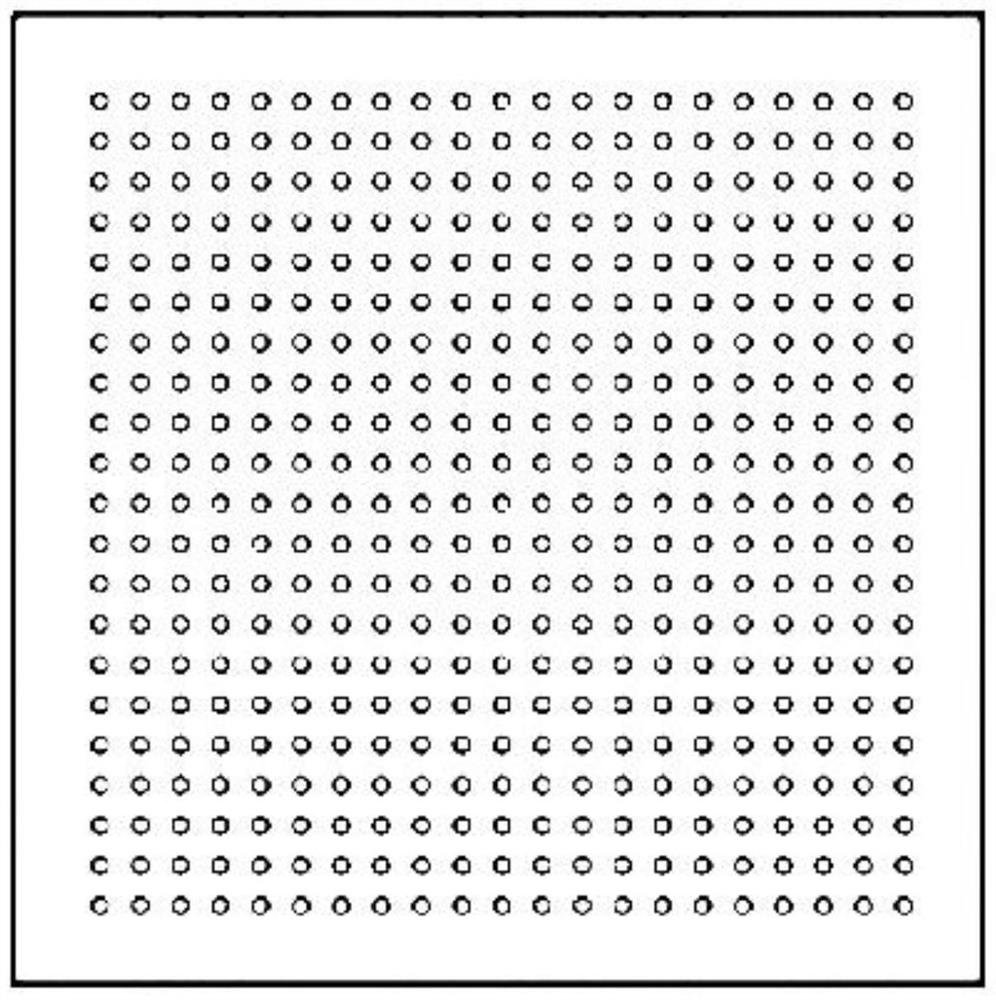
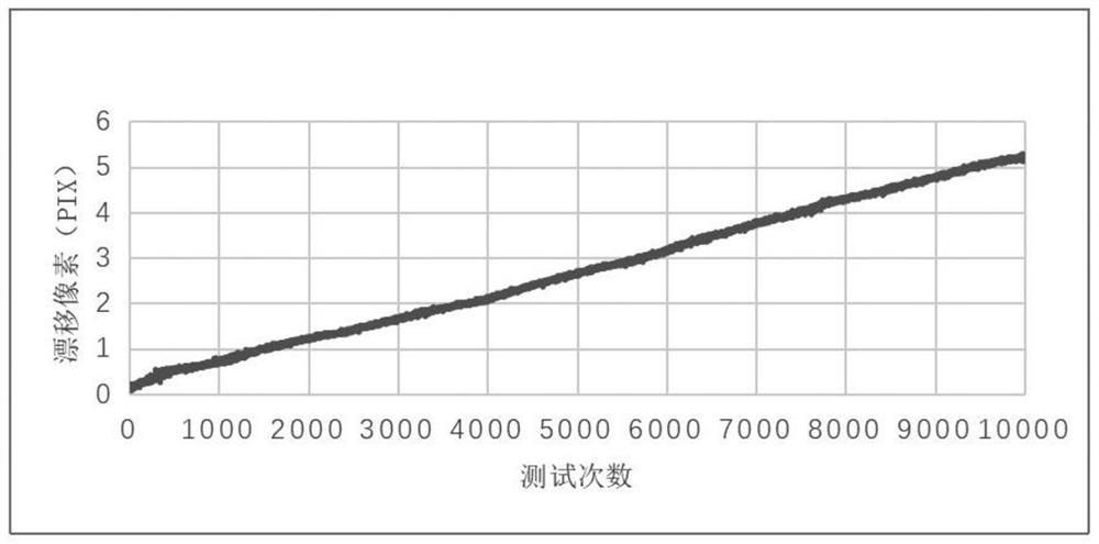
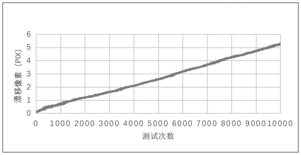
The invention relates to a micron-scale visual displacement calibration method, wherein the method comprises the steps: selecting an object space telecentric lens/or a double telecentric lens as an image acquisition tool, selecting two objects to be calibrated as a movable calibration object and a fixed calibration object respectively, acquiring images of the calibration objects by the lens, and calculating to obtain a central pixel coordinate of a mark point; and calculating the actual displacement value of the center pixel coordinate of the mark point after the position of the movable calibration object is moved by combining the displacement of the movable calibration object and the center pixel coordinate offset value of the mark point caused by the influence of the temperature on the fixed calibration object. The invention also relates to a micron-scale visual displacement calibration device comprising a camera, an object space telecentric lens/or double remote lenses, the movable calibration object and the fixed calibration object. The technical problem that the measurement precision is reduced under the influence of environment temperature and camera self-heating is solved, the high-precision measurement requirement of visual displacement calibration in a normal-temperature environment is met, and the measurement precision can reach +/-1 micron.

Description

technical field [0001] The invention belongs to the technical field of displacement calibration, and in particular relates to a displacement calibration method and device in a micron-level visual mode. Background technique [0002] By comparing two images on the surface of the same object (object to be calibrated) before and after movement, the corresponding displacement of the object to be calibrated can be obtained by using a two-dimensional digital image method. However, in the actual measurement, due to the deformation change of the surface of the object to be calibrated, the change of the ambient temperature, or the slight change of the camera sensor plane position caused by the self-heating of the camera, it is possible to make the original assumed linearity between the object plane and the image plane displacement The corresponding relationship is no longer strictly established, causing measurement errors that cannot be ignored, and it is difficult to meet the accurac...

Claims


Application Information

Patent Timeline
IPC IPC(8): G01B11/00
CPCG01B11/002
Inventor 赵少鹏林宪旗高岩刘建文周文静吴国良叶涛
Owner 济南蓝动激光技术有限公司
Why Eureka
Try Eureka