
Assembly method of circular grating

An assembly method and a circular grating technology, applied in the directions of installation, optics, optical components, etc., can solve the problems of limited image photo accuracy, difficult to meet the accuracy requirements of laser trackers, etc.

Active Publication Date: 2022-04-19
CHOTEST TECH INC
View PDF5 Cites 0 Cited by
  • Summary
  • Abstract
  • Description
  • Claims
  • Application Information

AI Technical Summary

Problems solved by technology

[0004] However, this method is limited by the accuracy of the image photo of the grating disc surface of the circular grating sensor, and it is difficult to meet the accuracy requirements of the laser tracker

Method used


Image

  • Assembly method of circular grating
  • Assembly method of circular grating
  • Assembly method of circular grating

Examples


Embodiment Construction

[0027] All references cited herein are incorporated by reference in their entirety as if fully set forth. Unless defined otherwise, technical and scientific terms used herein have the same meaning as commonly understood by one of ordinary skill in the art to which this invention belongs. A general guide to many of the terms used in this application is provided to those skilled in the art. Those skilled in the art will recognize many methods and materials similar or equivalent to those described herein, which could be used in the practice of the present invention. Indeed, the present invention is in no way limited to the methods and materials described.

[0028] The method for assembling the circular grating used to reduce the eccentricity error involved in the present invention will be described below with reference to the accompanying drawings.

[0029] The invention relates to an assembly method of a circular grating for reducing eccentricity errors, in particular to an as...


PUM


Abstract

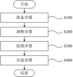
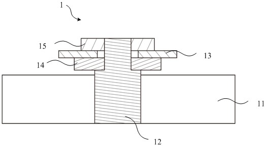
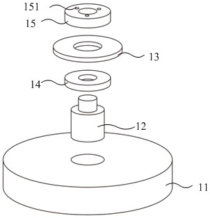
The invention provides a method for assembling a circular grating, comprising: arranging the circular grating on the grating rotation axis so that the circular grating can rotate relative to the base with the axis of the grating rotation axis as the rotation center; capturing and presenting a grating image having grating lines, adjusting the relative position of the circular grating to the axis of rotation of the grating so that an edge on one side of the grating image is moved within the dynamic range of the side edge; capturing an image of the circular grating in at least two positions The grating line image is converted into a first electrical signal and a second electrical signal, the eccentricity error of the circular grating is obtained based on the first electrical signal and the second electrical signal, and it is determined whether the eccentricity error is less than a preset threshold; and the installation step, if the eccentricity error If it is less than the preset threshold, the relative position of the circular grating and the grating rotation axis is fixed. In this case, the relative position of the circular grating and the grating rotation axis can be adjusted based on the difference between the circle center of the circular grating and the axis of the grating rotation axis.

Description

technical field [0001] The invention relates to an assembly method of a circular grating. Background technique [0002] The encoder made of circular gratings can accurately determine the angular position of the coordinates. Therefore, circular gratings are often used in laser trackers. Among the various error sources that affect the accuracy of the encoder, the eccentricity gap has a greater impact on the accuracy of the encoder, and the impact of the eccentricity gap on the accuracy of the encoder can be reduced through a suitable assembly method of the circular grating . [0003] In the prior art, the installation error of the circular grating is photographed by using the surface scribe lines of the circular grating, and the eccentricity of the grating disk is obtained based on the surface scribe lines of the circular grating. For example, CN201910278871.2 discloses a circular grating sensor angle measurement error correction method based on error source analysis, which ...

Claims


Application Information

Patent Timeline
Patent Type & Authority Patents(China)
IPC IPC(8): G02B7/00
CPCG02B7/00
Inventor 陈源廖学文张和君章智伟
Owner CHOTEST TECH INC
Learn More