Supercharge Your Innovation With Domain-Expert AI Agents!

Computer hardware detection equipment for judging tightness of keycap by utilizing suck-back

A technology of computer hardware and detection equipment, which is applied to the detection of faulty computer hardware, input/output of user/computer interaction, calculation, etc., and can solve problems such as manual judgment, scratches on the surface of keycaps, and unusable tightness of keyboard keycaps. And other problems, to avoid pinch damage, increase the effect of adsorption

Inactive Publication Date: 2021-08-31
杭州益星贸易有限公司
View PDF0 Cites 0 Cited by
  • Summary
  • Abstract
  • Description
  • Claims
  • Application Information

AI Technical Summary

Problems solved by technology

[0003] In the existing technology, the tightness of the keycaps of the keyboard affects the work efficiency of the programmer. The tightness of the keycaps of the keyboard cannot be judged manually. There is no fixed standard for manual judgment of the tightness of the keycaps, and the machine clamps and pulls the keys. There will be scratches on the surface of the keycaps, and the keyboard keycaps are not aligned with the detection equipment, which will affect the detection and judgment. Therefore, a computer hardware testing equipment that uses back suction to judge the tightness of the keycaps came into being.

Method used


Image

  • Computer hardware detection equipment for judging tightness of keycap by utilizing suck-back
  • Computer hardware detection equipment for judging tightness of keycap by utilizing suck-back
  • Computer hardware detection equipment for judging tightness of keycap by utilizing suck-back

Examples


Embodiment 1

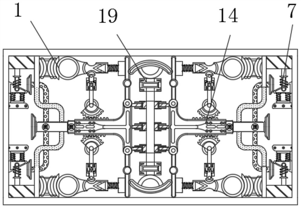
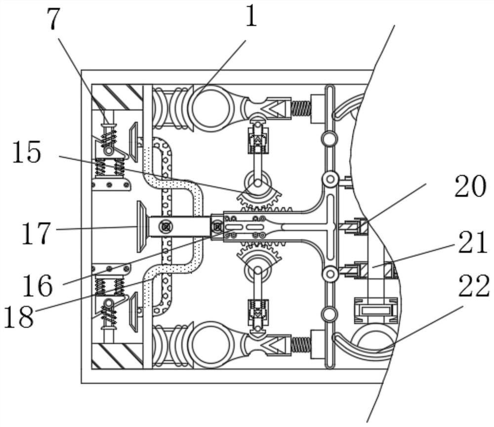
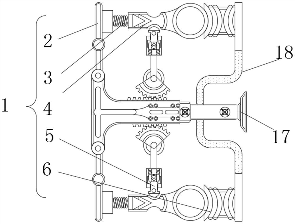
[0024] see Figure 1-3 , a computer hardware testing device for judging the tightness of keycaps by sucking back, comprising a suction mechanism 1 and a fixed key mechanism 7, the suction mechanism 1 includes a lever 2 fixedly connected to a compression spring 3 on the surface thereof, and the compression spring 3 is far away from the lever 2 One end of the ball plate 4 is fixedly connected with a ball plate 4, the surface of the ball plate 4 is clamped with a timing block 5, and the side of the ball plate 4 away from the stage clip 3 is fixedly connected with an air bag 6.

[0025] Further, the transmission mechanism 14 includes an incomplete gear 15, the surface of the incomplete gear 15 is movably connected with a T-shaped rack plate 16, and the surface of the T-shaped rack plate 16 is fixedly connected with a floppy disk 17, and the upper and lower sides of the floppy disk 17 are fixed. A hose 18 is connected.

[0026] The T-shaped rack plate 16 moves through the rotation...

Embodiment 2

[0028] see Figure 1-4 , a computer hardware testing device for judging the tightness of keycaps by sucking back, comprising a suction mechanism 1 and a fixed key mechanism 7, the suction mechanism 1 includes a lever 2 fixedly connected to a compression spring 3 on the surface thereof, and the compression spring 3 is far away from the lever 2 One end of the ball plate 4 is fixedly connected with a ball plate 4, the surface of the ball plate 4 is clamped with a timing block 5, and the side of the ball plate 4 away from the stage clip 3 is fixedly connected with an air bag 6.

[0029] Further, the fixed key mechanism 7 includes a crutch 8, the surface of the crutch 8 is fixedly connected with an extruding plate 9, the surface of the extruding plate 9 is movably connected with a slanting block 10, and the surface of the slanting block 10 is fixedly connected with a buffer spring 11, A control board 12 is fixedly connected to the side of the buffer spring 11 away from the slanting...

Embodiment 3

[0032] see Figure 1-5 ,

[0033] When in use, at first, the incomplete gear 15 rotates to make the T-shaped rack plate 16 move, the T-shaped rack plate 16 pushes the floppy disk 17 and makes the floppy disk 17 contact the keycap and deforms, and the floppy disk 17 is deformed to exhaust, so as to play a role in sticking. Close the keycap and form the effect of a closed space. When the floppy disk 17 moves to fit the keycap, the T-shaped rack plate 16 uses the lever 2 to stretch the compression spring 3. When the floppy disk 17 fits the keyboard keycap completely, the compression spring 3 The ball board 4 can be moved away from the restriction of the timing block 5, and enter into the ball part of the ball board 4. After bonding, the gas inside the airbag 6 is discharged by the hose 18 and the floppy disk 17, and the air pressure is used to Poor function of increasing the adsorption force.

[0034] Subsequently, the teeth of the incomplete gear 15 are no longer in contact wi...


PUM


Abstract

The invention relates to the technical field of computer hardware, and provides computer hardware detection equipment for judging the tightness of a keycap by means of suck-back. The computer hardware detection equipment comprises a pulling and sucking mechanism and a key fixing mechanism, the pulling and sucking mechanism comprises a lever, a pressure spring is fixedly connected to the surface of the lever, a ball plate is fixedly connected to one end, away from the lever, of the pressure spring, a timing block is clamped to the surface of the ball plate, and the side, away from the compressed spring, of the ball plate is fixedly connected with an airbag. According to the computer hardware detection equipment capable of judging the compactness of the keycap through suck-back, a T-shaped rack plate pushes a floppy disc to make the floppy disc make contact with the keycap and deform, the floppy disc deforms and exhausts to form a closed space, when the floppy disc moves to be attached to the keycap, the T-shaped rack plate stretches the pressure spring through the lever, gas in the airbag is exhausted through a hose and the floppy disc, the air pressure difference is utilized to increase the adsorption force, teeth of an incomplete gear do not make contact with the T-shaped rack plate any more, the T-shaped rack plate is reset by a reset rod spring, and the floppy disc starts to pull out the keycap.

Description

technical field [0001] The invention relates to the technical field of computer hardware, in particular to a computer hardware detection device for judging the tightness of keycaps by sucking back. Background technique [0002] The keyboard is an instruction and data input device used to operate computer equipment. The keyboard is a common computer hardware. Programmers can use the keyboard to give a series of instructions to the computer in real time. With the development of the times, there are various independent Keyboards with shortcut functions are sold with dedicated drivers and setting software, which can also realize personalized operations on compatible machines. [0003] In the existing technology, the tightness of the keycaps of the keyboard affects the work efficiency of the programmer. The tightness of the keycaps of the keyboard cannot be judged manually. There is no fixed standard for manual judgment of the tightness of the keycaps, and the machine clamps and ...

Claims


Application Information

Patent Timeline
IPC IPC(8): G06F3/02G06F11/22G01M13/00
CPCG01M13/00G06F3/0202G06F11/2221
Inventor 黄嘉琦
Owner 杭州益星贸易有限公司
Features
  • R&D
  • Intellectual Property
  • Life Sciences
  • Materials
  • Tech Scout
  • Unparalleled Data Quality
  • Higher Quality Content
  • 60% Fewer Hallucinations
Learn More