
Illuminating instrument for diagnostics, surgery or therapy

An instrument and surgical technology, applied in the field of lighting instruments, which can solve the problems of reduced light output, LED degradation, etc.

Pending Publication Date: 2021-08-31
DENTSPLY SIRONA INC +1
View PDF3 Cites 0 Cited by
  • Summary
  • Abstract
  • Description
  • Claims
  • Application Information

AI Technical Summary

Problems solved by technology

LED technology is more efficient than incandescent lamps, but when used in environments with limited cooling, overheating can lead to reduced light output and LED degradation

Method used


Image

  • Illuminating instrument for diagnostics, surgery or therapy
  • Illuminating instrument for diagnostics, surgery or therapy
  • Illuminating instrument for diagnostics, surgery or therapy

Examples


Embodiment Construction

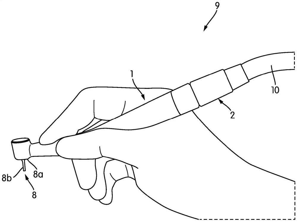
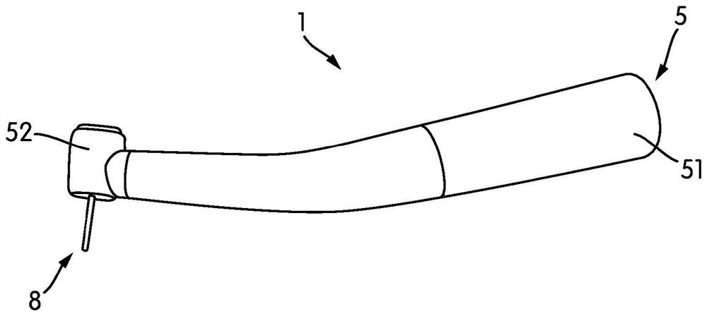
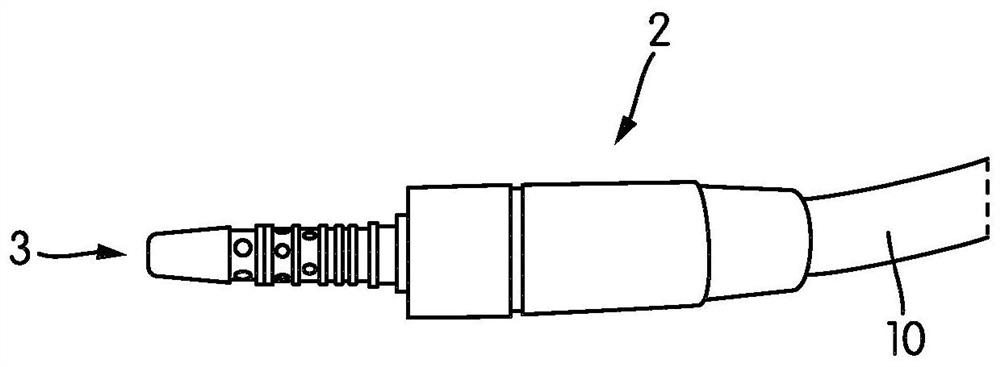
[0051] figure 1 A lighting system (9) according to an embodiment of the invention is shown. Such as Figure 2A and Figure 2B As shown, the lighting system (9) has a lighting device (1) and a coupling device (2). The lighting device (1) is suitable for diagnosis, treatment or surgery of a body part. A lighting instrument (1) is adapted for use with a coupling device (2). Such as Figure 2A and Figure 2B As shown, the lighting instrument (1) and the coupling device (2) are detachably attached. The housing (5) of the lighting instrument (1) can be detachably attached to the coupling device (2). Alternatively, the coupling device (2) may be fixed to the housing (5) such that the user cannot disassemble it. Such as Figure 2B As shown, the coupling device (2) has an electromagnetic radiation source (3) for generating electromagnetic radiation. The electromagnetic radiation source (3) is preferably an LED without an integrated phosphor element in direct contact with the ...


PUM


Abstract

The present invention relates to an illuminating instrument (1) for diagnostics, therapy or surgery of a body part, comprising: at least one optical fiber (4) for transmitting electromagnetic radiation directly from an electromagnetic radiation source (3) to the body part; and a housing (5) which supports the optical fiber (4); the optical axis of the light- output end of the optical fiber (4) circumferentially extends in an illumination portion (52a) in the housing (5) which is annular shaped and arranged to face the body part; the optical fiber (4) in the illumination portion (52a) has one or more diffusing regions (4a) for diffusing the electromagnetic radiation to the outside of the optical fiber (4) through the circumferential surface (4b) thereof, a coupling device (2) which supports the electromagnetic radiation source (3) for generating the electromagnetic radiation, characterized by further comprising: a conversion means (6) which is supported by the housing (5) without directly contacting the electromagnetic radiation source (3), and arranged between the diffusing regions (4a) and the body part for converting the electromagnetic radiation into visible light for illuminating the body part, and wherein the light-entrance end of the optical fiber (4) is directly optically connected with the electromagnetic radiation source (3), wherein the conversion means (6) is outside an optical interface between the light-entrance end of the optical fiber (4) and the electromagnetic radiation source (3).

Description

technical field [0001] The present invention relates to lighting instruments for diagnosis, surgery or therapy. The present invention more particularly relates to an illuminated dental instrument for drilling, scaling, painting and the like. Background technique [0002] Dental instruments used for drilling, scaling or spraying often require lighting so that the dentist can see clearly enough the area being treated. Any sharp edges and colored streaks in the lighting can cause the dentist's eyes to tire quickly. Furthermore, shadowing of the tools, ie, drills, scalers and air / water jets can make it difficult for the dentist to work. Therefore, it is often desirable to be able to illuminate relatively large areas intensively and uniformly. Due to the luminous efficiency of white LEDs, white LED technology is commonly used for the illumination of dental instruments. Most white LEDs are manufactured as phosphor-converted LEDs, which have a blue light-emitting diode covered ...

Claims


Application Information

Patent Timeline
Patent Type & Authority Applications(China)
IPC IPC(8): A61B1/05A61B1/06A61B1/07A61B1/24A61C1/08
CPCA61B1/05A61B1/0607A61C1/088A61B1/0676A61B1/0684A61B1/0623A61B1/07A61B1/24A61B1/063A61B1/0653A61C3/02A61C17/0202
Inventor M·西弗特B·厄梅A·欧策尔
Owner DENTSPLY SIRONA INC
Learn More