
Intelligent wearable equipment

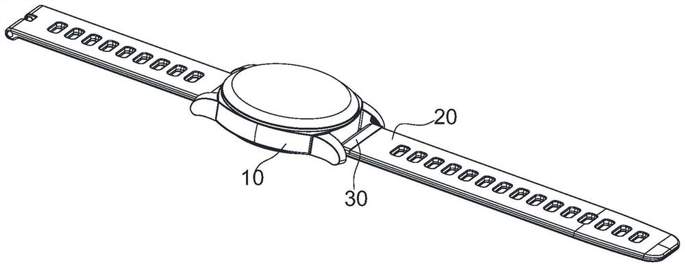
A smart wearable device and button technology, applied in the electronic field, can solve the problems of small design space of buttons, inconvenient size and setting position, and unfavorable pressing operation of buttons, and achieve the effect of improving convenience and function.

Pending Publication Date: 2021-09-03
WINGTECH COMM
View PDF0 Cites 0 Cited by
  • Summary
  • Abstract
  • Description
  • Claims
  • Application Information

AI Technical Summary

Problems solved by technology

[0002] With the continuous development of technology, smart wearable devices such as smart watches, children's watches, and smart bracelets are gradually becoming popular. Taking the existing smart watches as an example, they usually include wristbands, housings, and display screens. The display screens are installed on On the housing, the housing is connected to the wristband. In addition, buttons need to be configured on the housing. However, due to the small size of the smart watch’s housing itself, the design space reserved for the buttons is usually small. However, from the human In terms of mechanical engineering, smaller buttons are not conducive to the pressing operation of the human hand, and because the display screen is arranged on the front of the casing, the buttons are usually set on the side of the casing, and the operation of the consumer when pressing the button has a Larger limitations; In short, the buttons on the existing smart wearable devices cause a lot of inconvenience to users in terms of size and setting position

Method used


Image

  • Intelligent wearable equipment
  • Intelligent wearable equipment
  • Intelligent wearable equipment

Examples


Embodiment Construction

[0028] The following will clearly and completely describe the technical solutions in the embodiments of the present invention with reference to the accompanying drawings in the embodiments of the present invention. Obviously, the described embodiments are only part of the embodiments of the present invention, not all of them. Based on the embodiments of the present invention, all other embodiments obtained by persons of ordinary skill in the art without creative efforts fall within the protection scope of the present invention.

[0029] It should be noted that all directional indications (such as up, down, left, right, front, back...) in the embodiments of the present invention are only used to explain the relationship between the components in a certain posture (as shown in the accompanying drawings). Relative positional relationship, movement conditions, etc., if the specific posture changes, the directional indication will also change accordingly.

[0030] In addition, the ...


PUM


Abstract

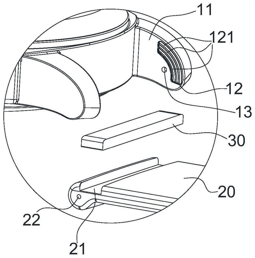
The invention discloses intelligent wearable equipment. The intelligent wearable equipment comprises a shell, a wrist strap and a key, wherein the shell is provided with two opposite connecting lugs, one end of the wrist strap is located between the two connecting lugs and connected with the two connecting lugs, one connecting lug is provided with a first contact terminal, and the first contact terminal is electrically connected with a mainboard in the shell; the key comprises a lower shell of the key and an upper shell of the key, the lower shell of the key is fixedly connected to one end of the wrist strap, a key FPC module and a second contact terminal are arranged on the lower shell of the key, and the second contact terminal extends to the outer surface of the lower shell of the key and is in contact conduction with the first contact terminal; and the upper shell of the key is movably installed on the lower shell of the key, and a top pressing part is arranged on the upper shell of the key. According to the invention, the key is arranged on the wrist strap, so the key has a larger pressing surface and is not limited by space and direction during pressing operation, and the convenience of operation is improved; and the key does not occupy the space of the shell, so more electronic devices can be implanted in the shell.

Description

technical field [0001] The invention relates to the field of electronic technology, in particular to an intelligent wearable device. Background technique [0002] With the continuous development of technology, smart wearable devices such as smart watches, children's watches, and smart bracelets are gradually becoming popular. Taking the existing smart watches as an example, they usually include wristbands, housings, and display screens. The display screens are installed on On the housing, the housing is connected to the wristband. In addition, buttons need to be configured on the housing. However, due to the small size of the smart watch’s housing itself, the design space reserved for the buttons is usually small. However, from the human In terms of mechanical engineering, smaller buttons are not conducive to the pressing operation of the human hand, and because the display screen is arranged on the front of the casing, the buttons are usually set on the side of the casing, ...

Claims


Application Information

Patent Timeline
Patent Type & Authority Applications(China)
IPC IPC(8): A44C5/00A44C5/14
CPCA44C5/0007A44C5/14
Inventor 顾硕郭彪但召华
Owner WINGTECH COMM
Learn More