
Drive-by-wire mechanism of double-gear water drainage valve

A drain valve and wire-controlled technology, applied in water supply devices, flushing equipment with water tanks, buildings, etc., can solve the problems of large swing rod 5 size, small center distance, and increased center distance, so as to achieve the small space required for installation , The overall structural strength is good, and the effect of precise thread control

Active Publication Date: 2013-09-18
XIAMEN R&T PLUMBING TECH
View PDF1 Cites 0 Cited by
  • Summary
  • Abstract
  • Description
  • Claims
  • Application Information

AI Technical Summary

Problems solved by technology

[0002] Chinese utility model patent (CN201241381Y) discloses a control device for double drain valves, a pressure receiving part 51 of a swing rod 5 and a control rod of a row of buttons 3 32 is opposite to the control rod 22 of the half-row button 2, and the lifting part 52 of the swing rod 5 is connected to one end of the traction rope 6, and the swing rod 5 can swing in different amplitudes through the different pressing strokes of the control rod 32 and the control rod 22, so that the swing rod 5 The lifting part 52 of the rod 5 pulls the traction rope 6 with different amplitudes, so that the traction rope 6 produces two different threads, and realizes the double drainage function of the wire-controlled drain valve; the disadvantage of this control device is: the full row of buttons 3 The center distance between the control rod 32 and the control rod 22 of the half-row button 2 is small, so the control rod 32 and the control rod 22 with a small center distance can act together on a small area of ​​the pressure plane 53 on the fork 5, The control rod 32 of the full row of buttons 3 is closely adjacent to the control rod 2 of the half row of buttons 2, so the area of ​​the full row of buttons 3 and the half row of buttons 2 cannot be made very large, so it is easy to cause misoperation when the manual row is pressed; but When setting a large interval between the full row of buttons 3 and the half row of buttons 2, the pressing area of ​​the full row of buttons 3 and the half row of buttons 2 can be made very large, and it is necessary to increase the control of the control rod 32 of the full row of buttons 3 and the half row of buttons 2 The distance between the centers of the rods 22, in this case, if the above scheme is still adopted, the swing rod 5 used will be larger in size and take up a larger space

Method used


Image

  • Drive-by-wire mechanism of double-gear water drainage valve
  • Drive-by-wire mechanism of double-gear water drainage valve
  • Drive-by-wire mechanism of double-gear water drainage valve

Examples


Embodiment 1

[0030] Embodiment one (The moving part adopts a connecting rod, the toggle device adopts a turntable, and the button seat and the wire control box are connected by a lock nut).

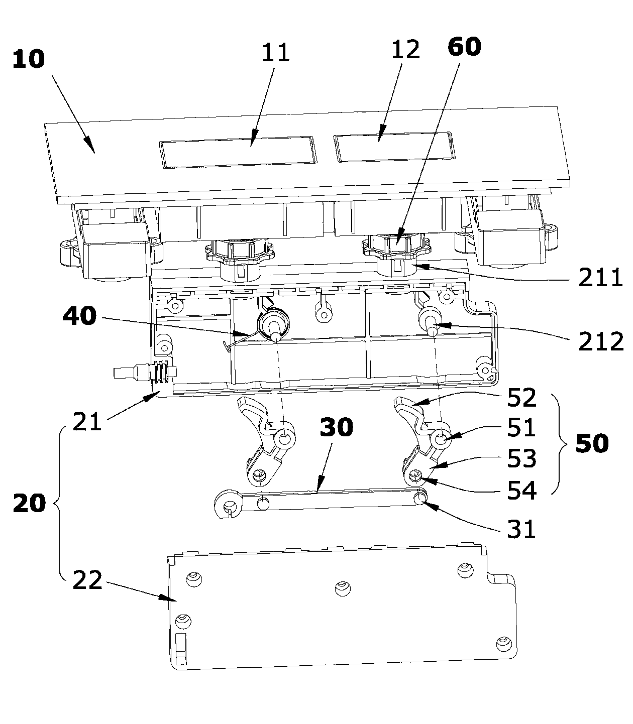
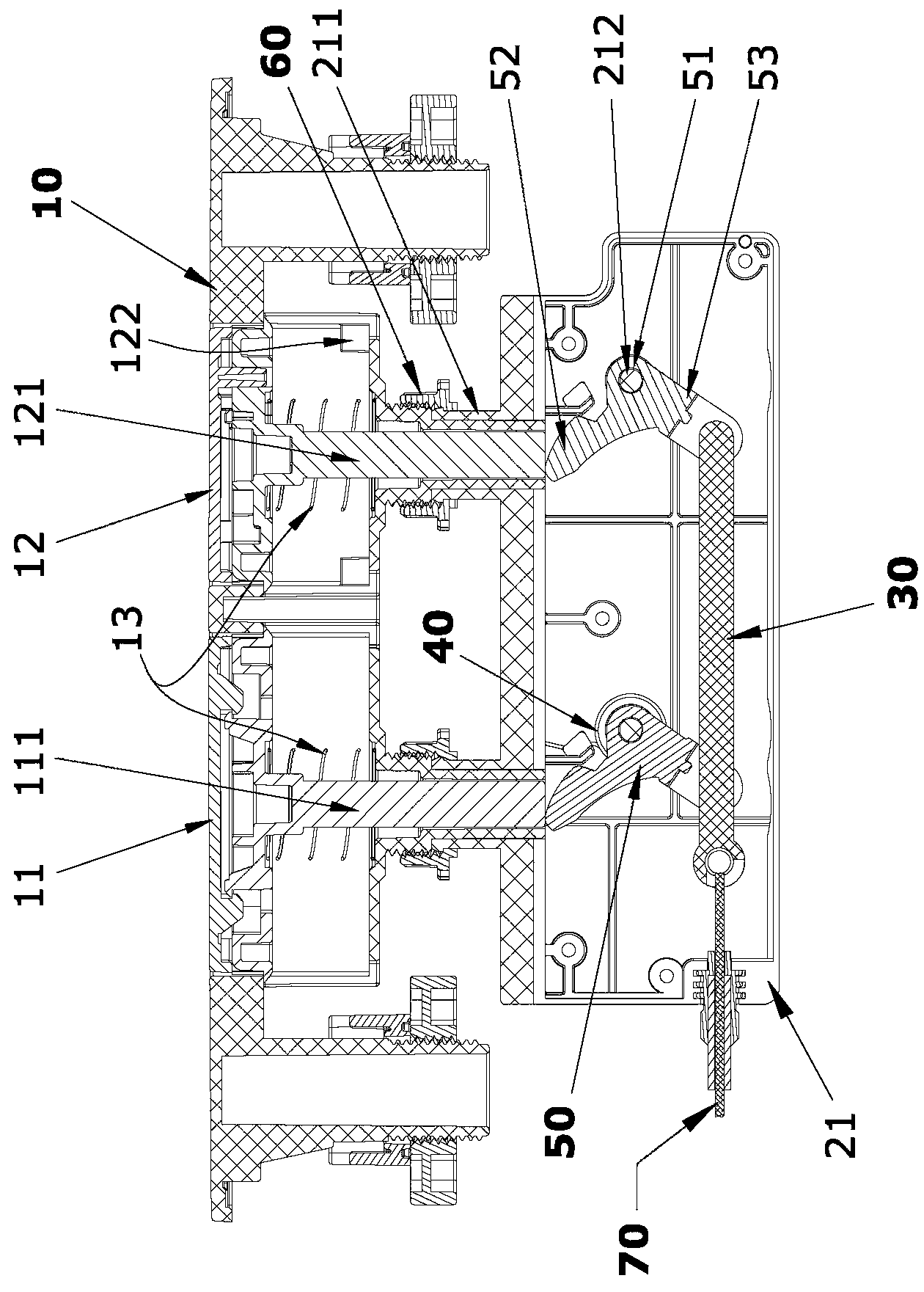
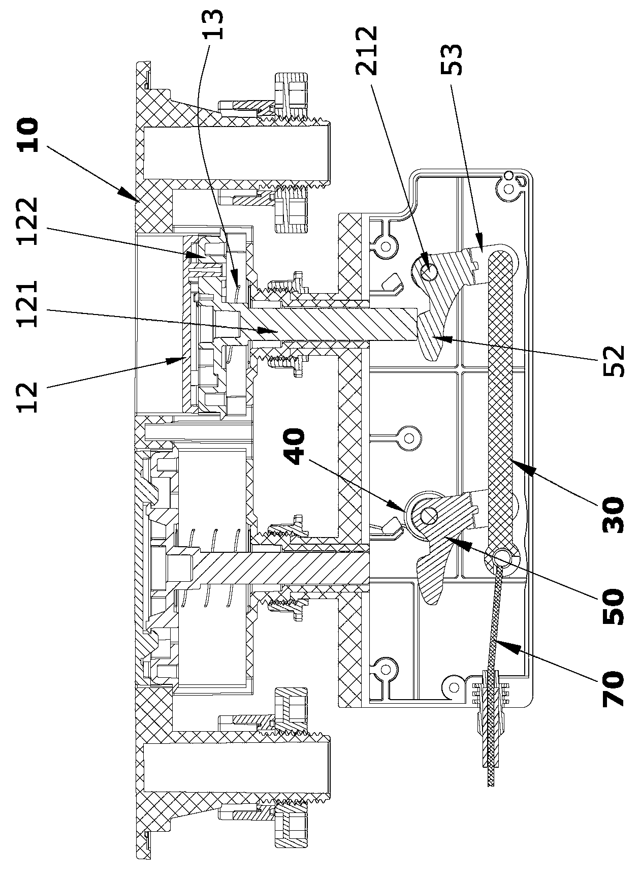
[0031] Such as figure 1 ~ Figure 4 A dual-speed drain valve wire control mechanism shown includes a button seat 10, a spring 13 is put on the full-row pressure rod 111 at the bottom of the full row of buttons 11, and is depressibly connected to the button seat 10, and the bottom of the half row of buttons 12 The half row of pressing rods 121 is also covered with a spring 13 that can be depressively connected to the button seat 10, and on the button seat 10, below the half row of buttons 12, a limit block 122 that limits the pressing stroke of the half row of buttons 12 is connected. Rows of buttons 11 and half rows of buttons 12 are arranged side by side, so that the center distance between the full row of pressing bars 111 at the bottom of the full row of buttons 11 and the half row of press...

Embodiment 2

[0034] Embodiment two (The moving part adopts a connecting rod, the toggle device adopts a turntable, and the button seat and the base shell of the wire control box are integrally formed).

[0035] Such as Figure 5 The difference between the two-speed drain valve wire control mechanism shown in the first embodiment is that the base shell 21 and the button seat 10 are integrally formed, and the sleeve 211 on the top of the base shell 21 and the connecting button seat 10 and the button seat 10 in the first embodiment are omitted. The locking nut 60 of the casing 211; other structures, working principles and implementation methods of this embodiment are the same as those of the first embodiment.

Embodiment 3

[0036] Embodiment three (The moving part adopts a slide bar, the toggle device is composed of the end face of the pressure bar and the guide slope on the slide bar, the button seat and the base shell of the wire control box are integrally formed, and the elastic part of the reset slide bar adopts a return spring).

[0037] Such as Image 6 ~ Figure 8 The difference between the two-speed drain valve wire control mechanism shown in the second embodiment is that the moving part is replaced by a connecting rod 30 with a sliding rod 32, one end of the sliding rod 32 is connected to the traction rope 70, and the other end is connected to the base shell 21. A return compression spring 41 is interposed as the return elastic member of the slide bar 32, and the two ends of the return compression spring 41 respectively resist the base shell 21 connected to the wire control box 20 and the slide bar 32 which can slide horizontally in the base shell 21; The toggling device of this e...


PUM


Abstract

Disclosed is a drive-by-wire mechanism of a double-gear water drainage valve. An all-drainage button and a half-drainage button which are respectively sleeved with two springs are mounted on a button seat side by side, the bottom of the button seat is connected with a drive-by-wire box, press rods at the bottoms of the all-drainage button and the half-drainage button are pressed into the drive-by-wire box, and a movable part which is parallel to a side-by-side direction of the all-drainage button and the half-drainage button is arranged in the drive-by-wire box, and is connected with a pulling rope; shifting devices which respond to pressing of the press rods so as to horizontally drive the movable part in one way are respectively between the all-drainage press rod and the movable part and between the half-drainage press rod and the movable part; an elastic part which leads the movable part to reset is disposed between the shifting devices or the movable part and the drive-by-wire box; and the arrangement and translation direction of the movable part for pulling the pulling rope is parallel to the side-by-side direction of the two buttons, the shifting devices which respond to pressing of the press rods to drive the movable part to move in one way are arranged between the press rod of the all-drainage button and the movable part and between the press rod of the half-drainage button and the movable part, the movable part translates but does not rotate, wire control is more accurate, the pitch between the two press rods is large, pressing surfaces of the two buttons are large, misoperation can be avoided, and the required space for installation is small.

Description

technical field [0001] The invention relates to a thread control mechanism for a wire-controlled drain valve, in particular to a wire-controlled mechanism for a dual-speed drain valve. Background technique [0002] Chinese utility model patent (CN201241381Y) discloses a control device for double drain valves. The pressure receiving part 51 of a swing rod 5 is opposite to the control rod 32 of the full row of buttons 3 and the control rod 22 of the half row of buttons 2. The swing rod 5 The lifting part 52 of the swing rod 5 is connected to one end of the traction rope 6, and the swing rod 5 is swung in different amplitudes through the different pressing strokes of the control rod 32 and the control rod 22, so that the lifting part 52 of the swing rod 5 pulls the pull rope 6 in different ranges. , so that the traction rope 6 produces two different threads to realize the double drainage function of the wire-controlled drain valve; the disadvantage of this control device is: th...

Claims


Application Information

Patent Timeline
Patent Type & Authority Patents(China)
IPC IPC(8): E03D5/09E03D1/34
Inventor 蒋友平王兴东王兵
Owner XIAMEN R&T PLUMBING TECH
Learn More