Method for verifying the operability of a safety valve

A safety valve, functional technology, applied in the field of checking the safety valve function, can solve the problem of not completing the manual partial stroke test

Pending Publication Date: 2021-09-03
SAMSON AG
View PDF6 Cites 0 Cited by
  • Summary
  • Abstract
  • Description
  • Claims
  • Application Information

AI Technical Summary

Problems solved by technology

Therefore, manual partial stroke testing is not done when in doubt or when absolu...

Method used


Image

  • Method for verifying the operability of a safety valve
  • Method for verifying the operability of a safety valve
  • Method for verifying the operability of a safety valve

Examples


Embodiment Construction

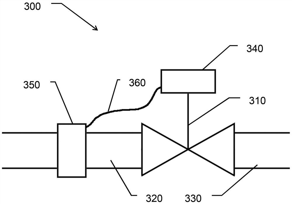
[0156] image 3 Process plant portion 300 is shown with safety valve 310 . During continuous operation of the plant, fluid process medium may be directed through section 300 or valve 310 . To this end, the valve 310 has an inlet 320 and an outlet 330 , wherein the process medium is guided into the safety valve 310 via the inlet 320 and out of the safety valve 310 again via the outlet 330 . The medium flow is controlled by means of a valve member (not explicitly shown) and a position regulator 340 which can move the valve member for this purpose. In continuous operation, the valve member is in a position that obstructs as little or as little as possible the flow of process media through the valve 310 . In the event of a disturbance, the safety valve 310 is closed by means of the position controller 340 , ie the valve member is moved by the position controller 340 into the closed position, so that process medium can no longer pass through the valve 310 .

[0157] The part 300...


PUM


Abstract

A method for verifying the operation of a safety valve(310) having a valve member and a positioner(340) for controlling the position of the valve member is proposed. The safety valve (310) is part of a plant on which a process with a process medium runs. The plant has a sensor (350)for monitoring the state of the plant, the procdess and the process medium. A sensor(350)'s measured value is used to determine a point in time during ongoing plant operation at which the operability of the valve (310) can be verified in the context of a partial stroke test. The test can also be monitored with the sensor(350) and the stroke range traversed therein can be dynamically adapted to the state. The test can thus be performed safely during operation and with an optimized stroke range. The method enables more frequent testing of and more reliable statements about the operability of the safety valve(310).

Description

technical field [0001] A regulating valve or regulating valve consists of a drive mechanism and a movable valve member. They are used to adjust fluid flow. Background technique [0002] The drive rod of the valve member is generally guided outwards through a fluid-tight housing or cover of the valve. Sealing (eg caulking) until the valve-housing-cover seals the drive rod outwardly. A drive mechanism is provided externally, which acts on the drive rod and moves the valve member. Typically, a fluid drive mechanism, typically a pneumatic drive mechanism, is used as the drive mechanism for moving the drive rod. The type of valve can be not only a rotary valve, but also a poppet valve. [0003] Different static and sliding frictions occur when the valve member is moved by the drive mechanism. Causes of friction may be: [0004] The seal between the drive rod and the valve-housing-cover, [0005] the friction between the drive rod and the drive housing seal, [0006] Rotar...

Claims


Application Information

Patent Timeline
IPC IPC(8): F15B19/00F15B20/00
CPCF15B19/005F15B20/00F16K37/0083F16K37/0091G01M13/003F16K37/0041
Inventor T·鲍尔
Owner SAMSON AG
Why Eureka
Try Eureka