Distribution pump arrangement for a hydraulic distribution system having changing flowing direction

A distribution pump, two-way hydraulic technology, used in fluid distribution devices, household appliances, heating systems, etc.

Active Publication Date: 2021-09-03
E ON SVERIGE
View PDF10 Cites 0 Cited by
  • Summary
  • Abstract
  • Description
  • Claims
  • Application Information

AI Technical Summary

Problems solved by technology

[0003] Determining the type of pumps and valves to use in a system that includes a bi-directional hydraulic distribution network and components for extracting heat from and / or storing heat in the bi-directional hydraulic distribution network presents design challenges

Method used


Image

  • Distribution pump arrangement for a hydraulic distribution system having changing flowing direction
  • Distribution pump arrangement for a hydraulic distribution system having changing flowing direction
  • Distribution pump arrangement for a hydraulic distribution system having changing flowing direction

Examples


no. 1 example

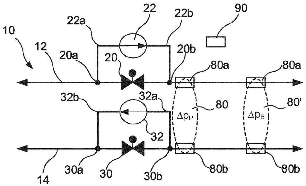
[0040] will combine figure 1 A first embodiment of a dispensing pump apparatus is discussed. According to this first embodiment, the distribution pump arrangement comprises a heat pipe control valve 20, a heat pipe distribution pump 22, pressure difference determining means 80, 80' and a controller 90. This first embodiment of the distribution pump apparatus is configured to reduce heat transfer from the hot conduit 12 to the cold conduit 14 when the partial pressure of the heat transfer fluid in the cold conduit 14 is higher than the partial pressure of the heat transfer fluid in the hot conduit 12 The partial pressure difference between fluids.

[0041] A heat pipe control valve 20 is arranged in the heat pipe 12 . Heat pipe control valve 20 may be controlled by controller 90 . The heat pipe control valve 20 can be set in an open state or a closed state. In the open state, the heat transfer fluid of the heat pipe 12 is allowed to flow through the heat pipe control ...

no. 2 example

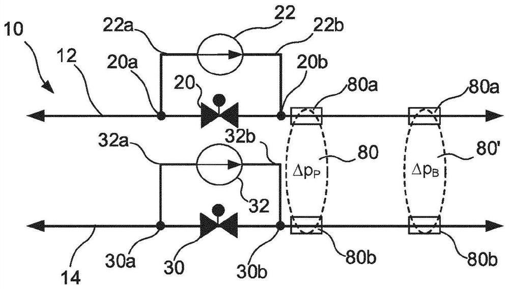
[0047] will combine figure 2 A second embodiment of a dispensing pump apparatus is discussed. In addition to the first embodiment of the dispense pump arrangement, this second embodiment further comprises a cold conduit control valve 30 and a cold conduit dispense pump 32 . As with the first embodiment of the dispense pump apparatus, this second embodiment is configured to reduce the pressure of the hot conduit 12 when the partial pressure of the heat transfer fluid in the cold conduit 14 is higher than the partial pressure of the heat transfer fluid in the hot conduit 12. The local pressure difference between the heat transfer fluid and the cold conduit 14.

[0048]A cold conduit control valve 30 is disposed in the cold conduit 14 . Cold conduit control valve 30 may be controlled by controller 90 . The cold conduit control valve 30 can be set in an open state or a closed state. In the open state, the heat transfer fluid of the cold conduit 14 is allowed to flow through t...

no. 3 example

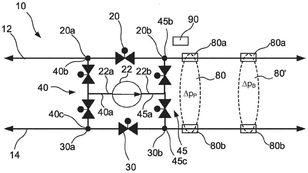
[0054] will combine image 3 A third embodiment of a dispensing pump apparatus is discussed. In addition to the first embodiment of the dispense pump apparatus, this third embodiment further includes a cold conduit control valve 30 , a first pump inlet valve assembly 40 , and a first pump outlet valve assembly 45 . As with the first embodiment of the dispense pump apparatus, this third embodiment is configured to reduce the pressure of the hot conduit 12 when the partial pressure of the heat transfer fluid in the cold conduit 14 is higher than the partial pressure of the heat transfer fluid in the hot conduit 12. The local pressure difference between the heat transfer fluid and the cold conduit 14. However, in addition to this, this third embodiment can also be configured to reduce the partial pressure of the heat transfer fluid in the heat pipe 12 when the partial pressure of the heat transfer fluid in the heat pipe 12 is higher than the partial pressure of the heat transfer...


PUM


Abstract

The present invention relates to a distribution pump arrangement for a bi-directional hydraulic distribution grid (10). The distribution pump arrangement comprises: a hot conduit control valve (20) in a hot conduit (12); a first distribution pump (22) having an inlet (22a) connected to the hot conduit (12) at a first side (20a) of the hot conduit control valve, and an outlet (22b) connected to the hot conduit (12) at a second side (20b), opposite the first side (20a), of the hot conduit control valve (20); a pressure difference determining device (80, 80') arranged beyond the second side of the hot conduit control valve (20) and configured to determine a local pressure difference, [delta]p, between a local pressure, p<hot>, of heat transfer liquid in the hot conduit (12) and a local pressure, p<cold>, of heat transfer liquid in the cold conduit (14); and a controller (90) configured to: while [delta]p < a threshold value, set the distribution pump arrangement in a flowing mode, wherein: the first distribution pump (22) is set to be inactive, and the hot conduit control valve (20) is set to be open, while [delta]p >= the threshold value and pcold > phot, set the distribution pump arrangement in a hot conduit pumping mode, wherein: the hot conduit control valve (20) is set to be closed, and the first distribution pump (22) is set to be active, thereby reducing the local pressure difference.

Description

technical field [0001] The invention relates to a distribution pump device for a two-way hydraulic distribution network. Background technique [0002] In recent years, two-way hydraulic distribution networks configured to distribute thermal energy to and from buildings in the area have been implemented. The applicant has registered under the trade mark ectogrid TM An example of such a two-way hydraulic distribution network is presented. ectogrid is further described in WO2017 / 076868 TM Two-way hydraulic distribution network. Such a bidirectional hydraulic distribution network includes a hot conduit configured to allow bidirectional flow of a heat transfer fluid at a first temperature therethrough, and a cold conduit configured to permit bidirectional flow of a heat transfer fluid at a second temperature therethrough. The second temperature is lower than the first temperature. Components for extracting heat from and / or storing heat in the two-way hydraulic distribution n...

Claims


Application Information

Patent Timeline
Patent Type & Authority Applications(China)
IPC IPC(8): F24D10/00F24D19/10G05D16/00
CPCF24D10/00F24D19/1006F24D2220/046G05D16/028G05D16/2073Y02B30/17F24D3/02F24D2220/02G05D16/208
Inventor 佩尔·罗森雅各布·斯科格斯特罗姆弗雷德里克·罗森奎斯特本特·林道夫
Owner E ON SVERIGE
Why Eureka
Try Eureka