
High-safety locking device capable of achieving hydraulic crusher maintenance conveniently

A hydraulic crushing and locking device technology, applied in grain processing, etc., can solve problems such as inability to absorb dust, accidents of maintenance personnel, screening blockage, etc., and achieve the effect of preventing personnel from being injured

Inactive Publication Date: 2021-09-07
广州普桔电气科技有限公司
View PDF0 Cites 0 Cited by
  • Summary
  • Abstract
  • Description
  • Claims
  • Application Information

AI Technical Summary

Problems solved by technology

[0002] Hydraulic crusher refers to the crushing machine whose particle size is greater than 3 mm in the discharge, accounting for more than 50% of the total discharge volume. The crushing operation is often divided into coarse crushing, medium crushing and fine crushing according to the size of the feeding and discharging particles. , and when the crusher is in the maintenance room, it can still rotate under the condition of external force, which may easily lead to accidents for maintenance personnel, so a specific locking device is required for assistance
[0003] When the crusher is running, it cannot absorb the dust generated inside the machine body, and the inside will be blocked during screening, resulting in low crushing efficiency. At the same time, the crushing roller will rotate freely due to external vibration during maintenance and cause harm to personnel. Therefore, in view of this , research and improve the existing structure and defects, and provide a high-safety locking device for hydraulic crusher maintenance, in order to achieve more practical value

Method used


Image

  • High-safety locking device capable of achieving hydraulic crusher maintenance conveniently
  • High-safety locking device capable of achieving hydraulic crusher maintenance conveniently
  • High-safety locking device capable of achieving hydraulic crusher maintenance conveniently

Examples


Embodiment Construction

[0019] The present invention will be further described below in conjunction with accompanying drawing:

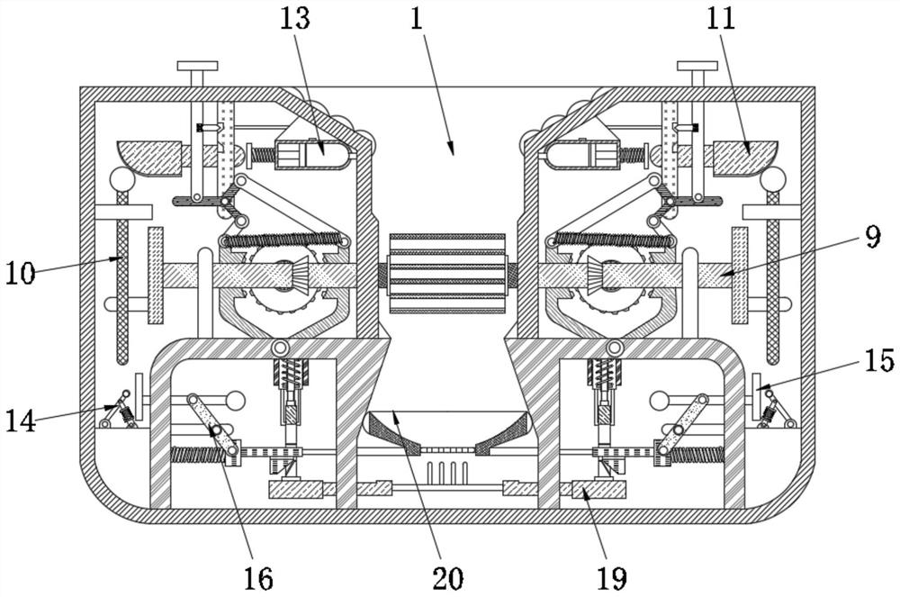
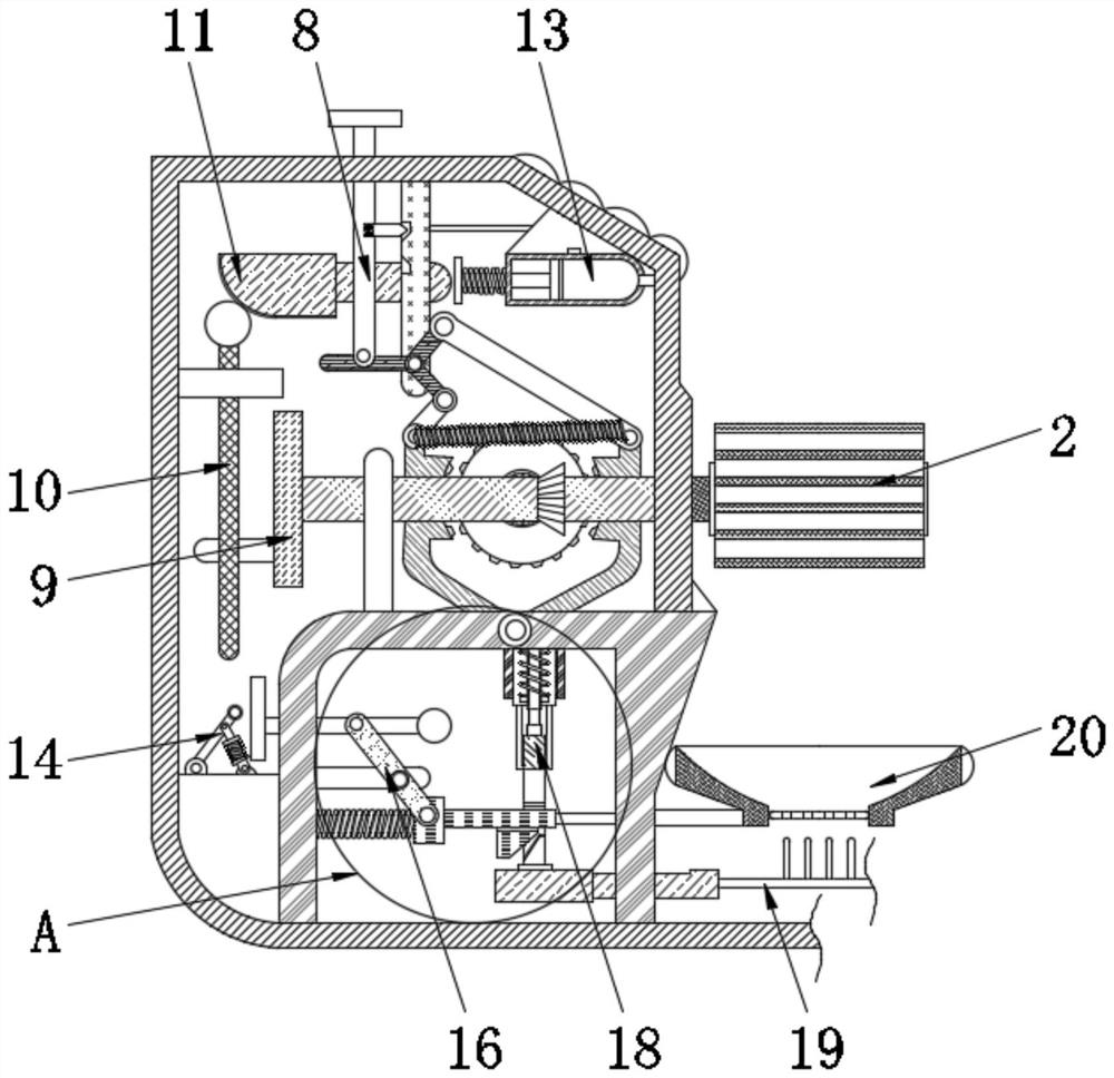
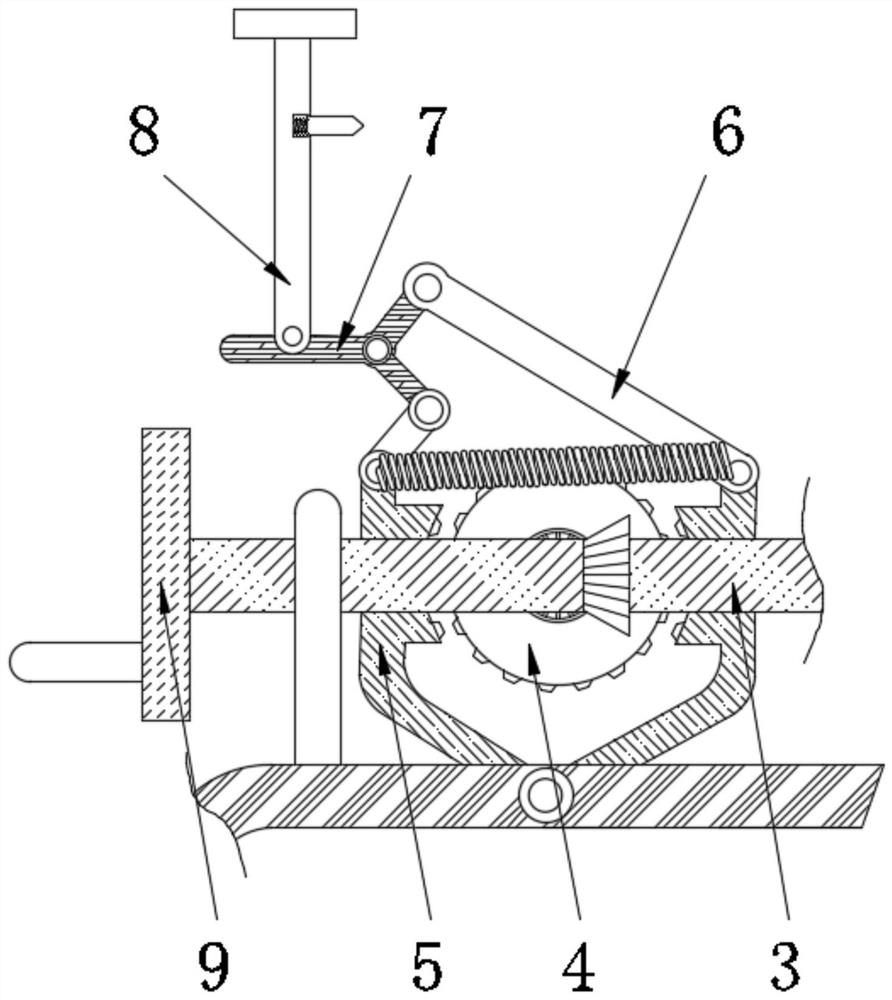
[0020] The invention provides a high-safety locking device convenient for hydraulic crusher maintenance, as attached figure 1 to attach Figure 4 Shown: includes the body 1, the body 1 is rotated and installed with the crushing roller 2, the left and right ends of the crushing roller 2 are fixedly installed with the transmission rod 3, the rear surface of the transmission rod 3 is engaged with the disc 4, and the left and right sides of the disc 4 Both are provided with clamping plates 5, and the connection between the front surface of the disc 4 and the transmission rod 3 is provided with a corresponding bevel gear, and the left and right sides of the transmission rod 3 and the inner wall of the clamping plate 5 are all provided with tooth blocks. A spring is fixedly connected between the adjacent clamping plates 5, and the bottom ends of the adjacent clamping plates 5 ar...


PUM


Abstract

The invention provides a high-safety locking device capable of achieving hydraulic crusher maintenance conveniently. Transmission rods are fixedly mounted at the left end and the right end of a crushing roller, the rear surfaces of the transmission rods are engaged with discs, clamped connection plates are arranged on the left side and the right side of each disc, the bottom ends of the adjacent clamped connection plates are movably connected, auxiliary rods are connected to the tops of the clamped connection plates, adjusting frames are movably connected to the top ends of the auxiliary rods, and pressing columns are movably mounted at the top ends of the adjusting frames. When a machine body is maintained, after the pressing columns are extruded downwards, spring clamping blocks on the surfaces of the pressing columns are in clamped connection with the machine body, and the pressing columns drive the adjusting frames to move downwards, the adjusting frames drive the auxiliary rods to move inwards, the clamped connection plates at the bottom ends of the auxiliary rods move inwards at the same time, and therefore the adjacent clamped connection plates are driven to be engaged with tooth blocks on the surfaces of the discs to limit rotation of the discs, the discs cannot drive the transmission rods to rotate, and therefore the situation that the crushing roller rotates freely due to outside vibration and hurts personnel is avoided.

Description

technical field [0001] The invention belongs to the technical field of hydraulic breakers, and in particular relates to a high-safety locking device convenient for maintenance of hydraulic breakers. Background technique [0002] Hydraulic crusher refers to the crushing machine whose particle size is greater than 3 mm in the discharge, accounting for more than 50% of the total discharge volume. The crushing operation is often divided into coarse crushing, medium crushing and fine crushing according to the size of the feeding and discharging particles. , and when the crusher is in the maintenance room, it can still rotate under the condition of external force, which is easy to cause accidents for maintenance personnel, so a specific locking device is required for assistance. [0003] When the crusher is running, it cannot absorb the dust generated inside the machine body, and the inside will be blocked during screening, resulting in low crushing efficiency. At the same time, t...

Claims


Application Information

Patent Timeline
IPC IPC(8): B02C4/00B02C4/28B02C23/10B02C23/18B02C23/04
CPCB02C4/00B02C4/28B02C23/10B02C23/18B02C23/04
Inventor 卢贝茜
Owner 广州普桔电气科技有限公司
Learn More