
Material belt film sticking machine

A film laminating machine and material tape technology, applied in the field of stamping and forming material belt processing equipment, can solve problems such as low efficiency and unstable film quality

Pending Publication Date: 2021-09-07
SUZHOU XINJIESHUN HARDWARE ELECTROMECHANICAL
View PDF0 Cites 0 Cited by
  • Summary
  • Abstract
  • Description
  • Claims
  • Application Information

AI Technical Summary

Problems solved by technology

Stamped products are usually connected with the material belt, and the product needs to be removed from the material belt through the reclaiming process; in order to ensure that the product will not fall during the reclaiming process, it is usually necessary to stick a film on the material belt. Currently, manual The way of sticking film is inefficient and the quality of sticking film is unstable

Method used


Image

  • Material belt film sticking machine
  • Material belt film sticking machine
  • Material belt film sticking machine

Examples


Embodiment

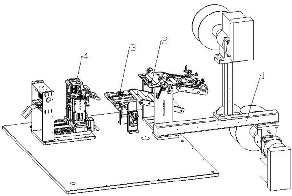
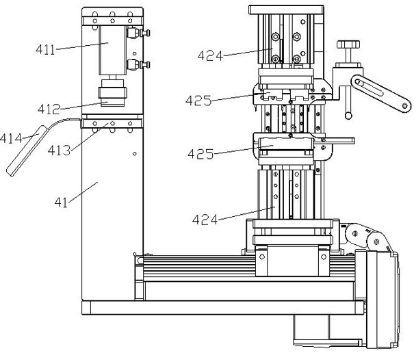
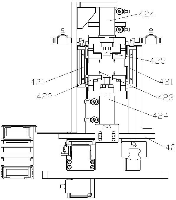
[0018] Such as Figure 1 to Figure 4 As shown, a tape laminating machine includes a film feeding module 1, a film stripping module 2, a material guide module 3 and a film pasting module 4 arranged sequentially along the advancing direction of the tape; the film stripping module 2 Including a film peeling support 21; the film peeling support 21 is provided with two sets of guide shafts and stripping knives 211; the film sticking module 4 includes a horizontal drive device, a film sticking base 42 and a positioning cylinder 421; the film sticking base 42 Set on the horizontal drive device; the positioning cylinder 421 is set on the film base 42 through a bracket; the positioning block 421 is provided with a positioning block 422; the positioning block 422 is provided with a positioning pin 423; the film base 42 Two film-sticking cylinders 424 are also arranged on it; the piston rods of the two film-sticking cylinders 424 are all provided with a film-sticking block 425; when the ...


PUM


Abstract

The invention relates to the technical field of automatic machining, and discloses a material belt film sticking machine which comprises a film feeding module, a film stripping module, a material guiding module and a film sticking module which are sequentially arranged in the advancing direction of a material belt. The film stripping module comprises a film stripping bracket. Upper and lower groups of material guide shafts and stripping knives are arranged on the film stripping bracket. The film sticking module comprises a horizontal driving device, a film sticking base and positioning air cylinders. The film sticking base is arranged on the horizontal driving device. The positioning air cylinders are arranged on the film sticking base through supports. Positioning blocks are arranged on the positioning air cylinders. Positioning pins are arranged on the positioning blocks. The film sticking base is further provided with two film sticking air cylinders. Piston rods of the two film sticking air cylinders are each provided with a film sticking pressing block. When the piston rods of the two film sticking air cylinders stretch out, the two film sticking pressing blocks are attached. A pressing device is arranged on the side, away from the material guiding module, of a positioning film sticking device.

Description

technical field [0001] The invention relates to a processing equipment for stamping and forming material strips, in particular to a material strip film laminating machine. Background technique [0002] With the maturity of stamping technology, stamping forming has become scientific, data-based and controllable, and more and more products are manufactured through stamping forming process. Stamped products are usually connected with the material belt, and the product needs to be removed from the material belt through the reclaiming process; in order to ensure that the product will not fall during the reclaiming process, it is usually necessary to stick a film on the material belt. Currently, manual The way of sticking film is inefficient and the quality of sticking film is unstable. Contents of the invention [0003] The technical problem to be solved by the present invention is to provide a material tape film laminating machine, which can automatically bond the film and th...

Claims


Application Information

Patent Timeline
IPC IPC(8): B65B33/02
CPCB65B33/02
Inventor 姜智勤
Owner SUZHOU XINJIESHUN HARDWARE ELECTROMECHANICAL
Learn More