Needle-piercing mechanism and its carrier

A carrier and body technology, applied in the field of testing equipment, can solve the problems of increased cost, troublesome PCB board clamping and positioning operations, etc., and achieve the effects of high clamping and positioning accuracy, convenient operation, and cost reduction

Active Publication Date: 2022-07-19
GUANGDONG TOPSTAR TECH
View PDF13 Cites 0 Cited by
  • Summary
  • Abstract
  • Description
  • Claims
  • Application Information

AI Technical Summary

Problems solved by technology

[0005] However, in the existing carrier board, the PCB board is clamped and positioned by the clamping and positioning groove and the connecting wire is positioned by the wire positioning groove. It requires a manipulator and an auxiliary CCD device to accurately place the PCB board. In the clamping and positioning groove, on the one hand, it increases the cost, on the other hand, it makes the PCB board clamping and positioning operation troublesome

Method used


Image

  • Needle-piercing mechanism and its carrier
  • Needle-piercing mechanism and its carrier
  • Needle-piercing mechanism and its carrier

Examples


Embodiment Construction

[0031] In order to describe the technical content and structural features of the present invention in detail, further description will be given below with reference to the embodiments and the accompanying drawings.

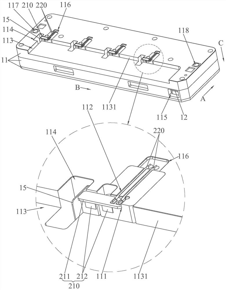
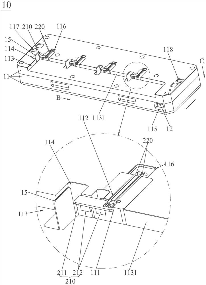
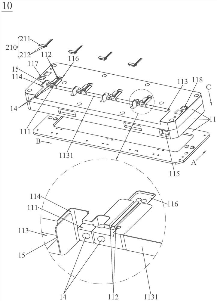
[0032] see Figure 1 to Figure 4 , the carrier 10 of the present invention includes a carrier body 11 , a sliding rod 12 , an elastic member 13 , a magnet 14 and a push piece 15 . The top of the carrier body 11 is provided with a PCB positioning groove 111 for positioning the PCB board 210 , a wire positioning groove 112 for positioning the connecting wire 220 soldered to the PCB board 210 , and a groove for sinking the top of the carrier body 11 . The sinking avoidance cavity 113 and the movable cavity 114 for the ejector sheet 15 to move. The sinking avoidance cavity 113 is located directly in front of the PCB positioning slot 111 in a communication manner, so that the sinking avoidance cavity 113 is located directly in front of the PCB positioning slot 111 and ...


PUM


Abstract

The invention discloses a carrier, comprising a carrier body, a sliding rod, an elastic piece, a magnet and a push piece. The top of the carrier body is provided with a PCB positioning slot, a wire positioning slot, a sinking avoidance cavity and a movable cavity; the sinking avoidance cavity is located directly in front of the PCB positioning slot, and the wire positioning slot is located directly behind the PCB positioning slot; the movable cavity is located on the PCB On the left or right side of the positioning groove, the sliding rod is slidably arranged on the carrier body along the left and right directions of the carrier body and can be slidably switched between the first position and the second position. The rod is assembled and connected; the elastic piece is set between the sliding rod and the carrier body, and the elastic piece always has the tendency to drive the sliding rod and the push piece to slide to the second position, and the magnet is assembled on the side cavity wall behind the sinking escape cavity , when the push piece is in the second position, the PCB board in the PCB positioning slot is pressed tightly; in order to achieve the purpose of precise positioning and clamping. In addition, the present invention also discloses a supporting needle sticking mechanism.

Description

technical field [0001] The invention relates to a test equipment, in particular to a needle-piercing mechanism for supporting the test equipment and a carrier thereof. Background technique [0002] With the continuous development of the economy and the continuous progress of the society, various material consumer goods are provided for people's lives, and electronic products are one of the many material consumer goods. [0003] As we all know, smartphones, tablets, laptops, etc. are all electronic products. Among them, for the smart phone, it cannot be used without the power protection board of the mobile phone. In the production process of the mobile phone power protection board, it is inseparable to use the pin pinning device in the test equipment to pin the free end of the soldered PCB board and the connection line in the connection line, so as to meet the needs of the soldered PCB. Boards and cables for performance testing. [0004] In order to make the work between t...

Claims


Application Information

Patent Timeline
Patent Type & Authority Patents(China)
IPC IPC(8): G01R31/28G01R1/04G01R1/073
CPCG01R31/2808G01R1/0408G01R1/07328
Inventor 王钊邹启帆张坤曾佳立吴丰礼
Owner GUANGDONG TOPSTAR TECH
Why Eureka
Try Eureka