A high resistance chip resistor
A chip resistor, high resistance technology
- Summary
- Abstract
- Description
- Claims
- Application Information
AI Technical Summary
Problems solved by technology
Method used
Image

Examples
Embodiment 1
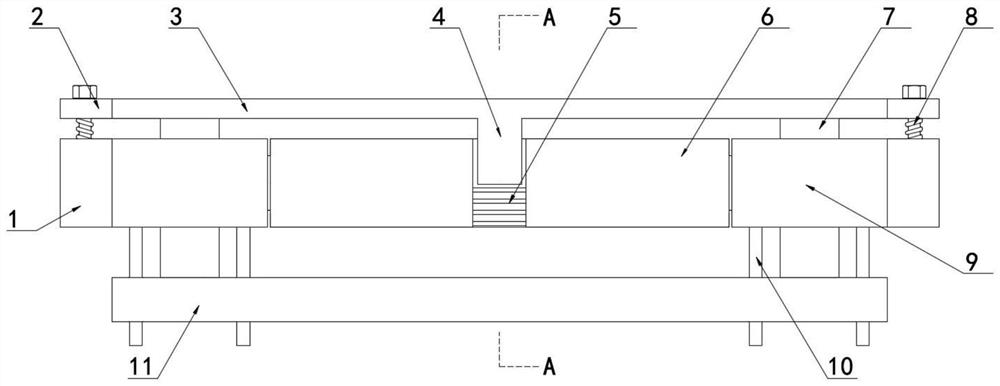
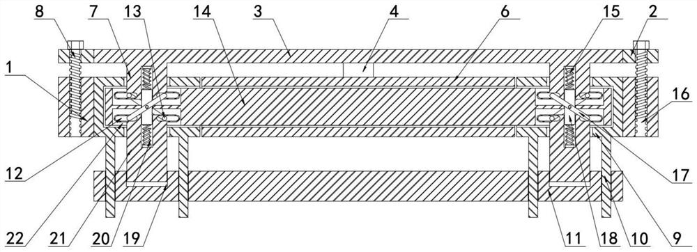
[0038] Example 1, refer to Figure 1-5 , a high-resistance chip resistor, including a chip resistor inner shell 14 and a circuit board lower board 11 set at the chip resistor inner shell 14, and the chip resistor inner shell 14 is sleeved with two There are side protective shells 6, two side inner frames 9 are respectively sleeved on the left and right sides of the inner shell 14 of the chip resistor, the inner shell 14 of the chip resistor is provided with a chip guide groove 22, and the inner shell 14 of the chip resistor is provided with a chip guide groove 22. A dust-proof upper cover 3 is arranged above, an upper insertion rod 7 is fixedly connected to the lower end of the dust-proof upper cover 3, a lower contact slot 19 is opened on the lower board 11 of the circuit board, and a lower insertion rod 21 is sleeved on the lower contact slot 19. , the ends of the lower insertion rod 21 and the upper insertion rod 7 that are close to each other are fixedly connected with a h...
Embodiment 2
[0039] Embodiment 2, refer to Figure 1-5 , a guide slot 23 is provided at the joint between the two side protective shells 6, the two side protective shells 6 are inserted through the guide slot 23, and the inner cavity of the patch guide groove 22 slides with the lateral inner chute plate 12 Connection, the lateral inner chute plate 12 is in contact with the inner wall of the patch guide groove 22, and the side of the two side protective shells 6 away from each other is provided with a side extrusion deflection guide groove 5, and the dust-proof upper cover plate 3 The side surfaces are fixedly connected with a squeeze lock 4, the squeeze lock 4 is in contact with the side squeeze deflector groove 5, the two side protective shells 6 are in an open box structure, and the two side protective shells 6 have inner cavities. They are all slidably connected to the inner shell 14 of the chip resistor. The side extrusion deflection guide groove 5 fits the extrusion lock piece 4 and t...
Embodiment 3
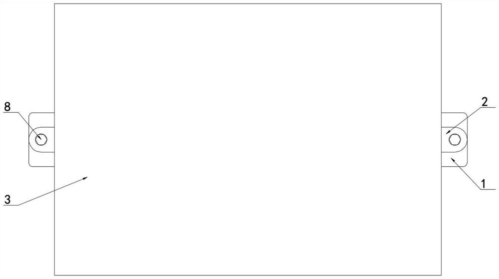
[0040] Embodiment 3, refer to Figure 1-5 , the left and right sides of the dust-proof upper cover plate 3 are fixedly connected with the connecting upper seat 2, the side walls of the two side inner frames 9 away from each other are fixedly connected with the connecting lower seat 1, and the two connecting lower seats 1 are respectively connected with two The upper connecting seat 2 is set on the same vertical plane, the upper connecting seat 2 is sleeved with a locking threaded rod 8, the lower connecting seat 1 is provided with a mounting threaded groove 16, and the lower end of the locking threaded rod 8 is screwed with the mounting threaded groove 16. Connection, the inner cavity between the upper insertion rod 7 and the lower insertion rod 21 is fixedly connected with a squeeze contact rod 15, and the outer sides of the two squeeze contact rods 15 are sleeved with a buffer compression spring 20, which presses the top rod longitudinally. The two ends of 18 are respectivel...
PUM
 Abstract
Description
Claims
Application Information