
Belt head adjusting mechanism for metal belts and continuous conveying equipment for metal belts

A technology for adjusting mechanisms and conveying equipment, which is applied in metal processing equipment, welding equipment, welding equipment, etc., and can solve problems such as inability to align, uncertain bending direction, and bending of the steel strip head

Pending Publication Date: 2021-09-10
BEIJING NEW BUILDING MATERIALS PLC
View PDF8 Cites 0 Cited by
  • Summary
  • Abstract
  • Description
  • Claims
  • Application Information

AI Technical Summary

Problems solved by technology

[0002] In the existing steel belt continuous transmission equipment, when the front steel belt is delivered to the belt tail, the belt tail is controlled to stop at the welding mechanism, and then the welding mechanism needs to manually connect the head of the rear steel belt to the belt of the front steel belt. Tail alignment (the reason is: the thickness of the steel strip is thin, the strip head will be bent, and the bending direction is uncertain, so the strip head cannot be sent to the welding machine through the feeding mechanism to align with the strip tail of the front side steel strip, only Manually align the head of the rear steel belt with the tail of the front steel belt), and then weld the tail of the front steel belt and the head of the rear steel belt together through the welding mechanism, and then control the steel belt to continue teleport forward

Method used


Image

  • Belt head adjusting mechanism for metal belts and continuous conveying equipment for metal belts
  • Belt head adjusting mechanism for metal belts and continuous conveying equipment for metal belts
  • Belt head adjusting mechanism for metal belts and continuous conveying equipment for metal belts

Examples


Embodiment Construction

[0028] The application describes a number of embodiments, but the description is illustrative rather than restrictive, and it will be obvious to those of ordinary skill in the art that within the scope of the embodiments described in the application, There are many more embodiments and implementations. Although many possible combinations of features are shown in the drawings and discussed in the detailed description, many other combinations of the disclosed features are possible. Except where expressly limited, any feature or element of any embodiment may be used in combination with, or substituted for, any other feature or element of any other embodiment.

[0029] This application includes and contemplates combinations of features and elements known to those of ordinary skill in the art. The disclosed embodiments, features and elements of this application can also be combined with any conventional features or elements to form unique inventive solutions as defined by the clai...


PUM


Abstract

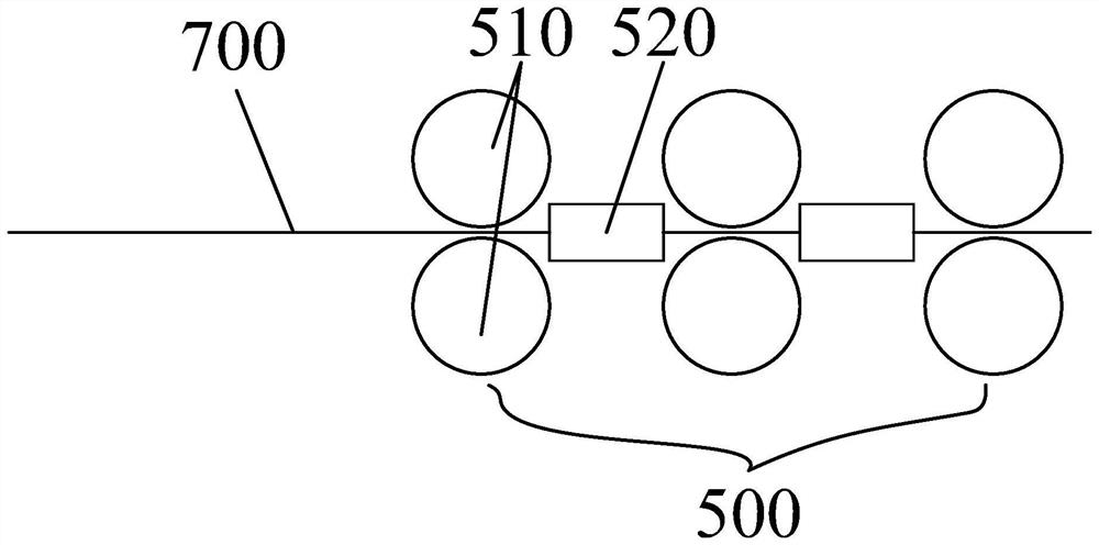
The invention provides a belt head adjusting mechanism for metal belts and continuous conveying equipment for the metal belts. The belt head adjusting mechanism comprises multiple belt pressing roller sets which are arranged front and back at intervals and first guide channels arranged between the adjacent belt pressing roller sets. According to the belt head adjusting mechanism, the rear-side metal belt is conveyed forwards through the multiple belt pressing roller sets and the first guide channels, and the multiple belt pressing roller sets press the belt head of the rear-side metal belt to adjust the bending direction of the belt head of the rear-side metal belt, so that the belt head of the rear-side metal belt is pressed by the multiple belt pressing roller sets, then extends out of the multiple belt pressing roller sets in the set direction and stops at the belt tail of the front-side metal belt, and automatic alignment of the belt head of the rear-side metal belt and the belt tail of the front-side metal belt is achieved.

Description

technical field [0001] This article relates to the technical field of mechanical equipment, in particular to a belt head adjustment mechanism for metal belts and a continuous transmission equipment for metal belts. Background technique [0002] In the existing steel belt continuous transmission equipment, when the front steel belt is delivered to the belt tail, the belt tail is controlled to stop at the welding mechanism, and then the welding mechanism needs to manually connect the head of the rear steel belt to the belt of the front steel belt. Tail alignment (the reason is: the thickness of the steel strip is thin, the strip head will be bent, and the bending direction is uncertain, so the strip head cannot be sent to the welding machine through the feeding mechanism to align with the strip tail of the front side steel strip, only Manually align the head of the rear steel belt with the tail of the front steel belt), and then weld the tail of the front steel belt and the he...

Claims


Application Information

Patent Timeline
IPC IPC(8): B23K31/02B23K37/00B23K37/047
CPCB23K37/047B23K37/00B23K31/02
Inventor 陈浩刘受志建军
Owner BEIJING NEW BUILDING MATERIALS PLC
Learn More