Focusing structure

A technology of slotting and connecting blocks, which is applied in the field of focusing structure, can solve the problems of reducing the focusing speed of the lens and low rotation efficiency

Pending Publication Date: 2021-09-10
JIAXING ZHONGRUN OPTICAL TECH
View PDF0 Cites 0 Cited by
  • Summary
  • Abstract
  • Description
  • Claims
  • Application Information

AI Technical Summary

Problems solved by technology

[0002] The implementation of manual zoom / focus usually adopts a single-layer CAM structure. After confirming the group movement stroke and the required rotation angle, a linear CAM or a curved CAM will be designed. In order to ensure smooth and stable driving, the CAM movement stroke It is mutually restricted with the required rotation angle. When the movement stroke of the moving group is fixed, when the angle between the curve and the bottom surface of the CAM cylinder is too large, a large rotational torque is required to move the group. Therefore, the clamping angle between the curve and the bottom surface of the CAM cylinder The angle generally does not exceed 45°, the rotation angle of the CAM tube is small, the curve is straight, the rotation efficiency is low, and the focusing speed of the lens is reduced

Method used


Image

  • Focusing structure
  • Focusing structure
  • Focusing structure

Examples


Embodiment 1

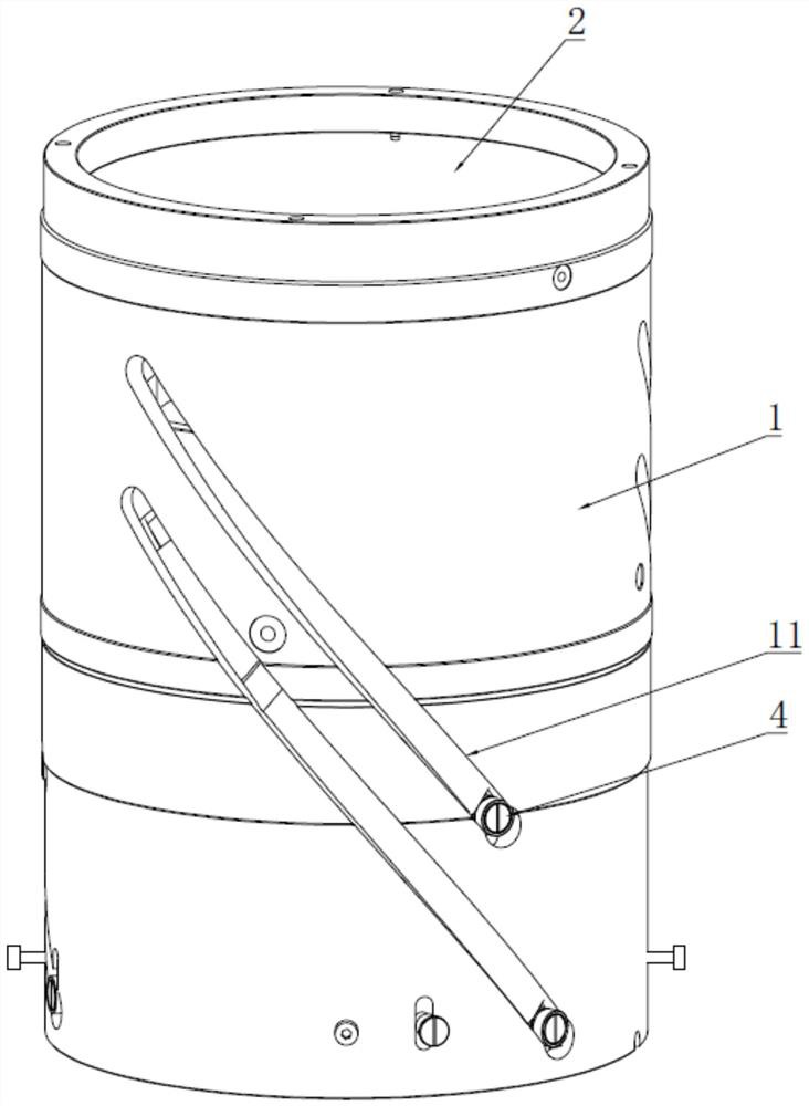
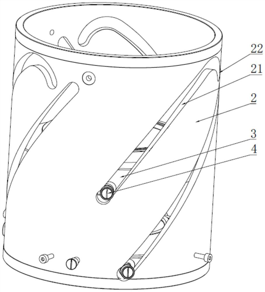
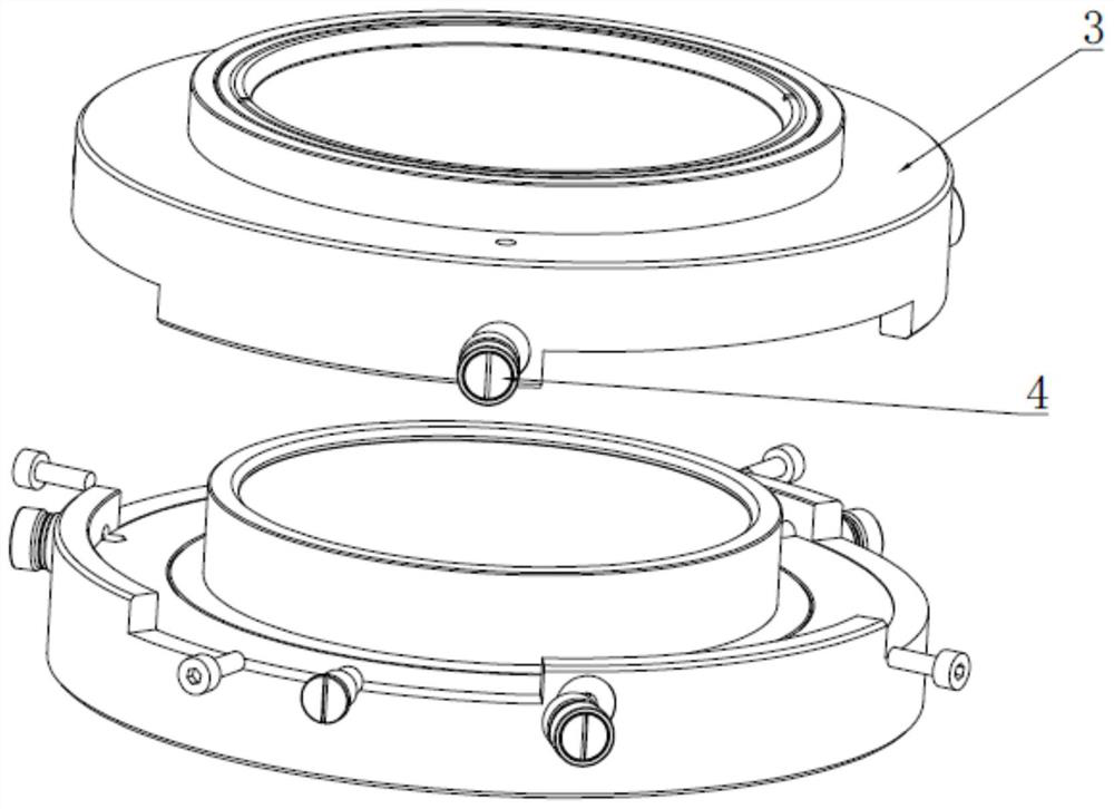
[0045] Such as Figure 1 to Figure 3 As shown, a focusing structure includes a coaxial fixed cylinder 1, a connecting cylinder 2 and a moving group 3. In this embodiment, the fixed cylinder 1 is arranged on the outermost side, and the connecting cylinder 2 is arranged on the inner side of the fixed cylinder 1. The moving group 3 is arranged in the connecting cylinder 2; the connecting cylinder 2 is provided with a first sub-groove 21, and the fixed cylinder 1 is provided with a second sub-groove 11, and the first sub-groove 21 and the second sub-groove are connected to each other. The rotation directions of the grooves 11 are opposite. In this embodiment, the first sub-grooves 21 are opened in a right-handed direction, and the second sub-grooves 11 are opened in a left-handed direction.

[0046] The moving group 3 is provided with a first connecting block 64, and the first connecting block 64 is slidably connected to the first sub-groove 21.

[0047] Optionally, the fixed cyl...

Embodiment 2

[0053] On the basis of Example 1, such as Figures 2 to 5 As shown, in this embodiment, when the first connecting block 64 slides in the first sub-groove 21 along the rotation direction of the first sub-groove 21, the connecting cylinder 2 moves along the second sub-groove. The opening direction of 11 is rotated.

[0054] In this embodiment, the sliding of the first connecting block 64 can drive the connecting cylinder 2 to rotate along the opening direction of the second sub-groove 11, that is, the connecting cylinder 2 can move along the axis of the connecting cylinder 2, and the moving group When the moving stroke of 3 is fixed, the rotation angle of the connecting cylinder 2 is further reduced, the time required for the connecting cylinder 2 to rotate is reduced, the rotating efficiency of the connecting cylinder 2 is increased, and the focusing speed of the lens is increased.

[0055] The fixing cylinder 1 is further provided with a limiting groove 12, the limiting groov...

Embodiment 3

[0067] On the basis of embodiment 1 or 2, such as Figure 1 to Figure 5 As shown, the second sub-groove 11 is a helix; and / or the first sub-groove 21 is a helix.

[0068] By setting the first sub-groove 21 and / or the second sub-groove 11 as a helical line, when the connecting cylinder 2 rotates at a constant speed, it drives the moving group to rotate at a constant speed, which increases the reliability of the focusing structure during movement.

[0069] One or more first sub-grooves 21 are provided, and the spacing between adjacent first sub-grooves 21 along the axis direction of the connecting cylinder 2 is the same as the lens spacing of the lenses in the corresponding state.

[0070] Through the setting of a plurality of first sub-slots 21, the synchronous movement of a plurality of mobile groups 3 has been realized, and the moving efficiency of the mobile groups 3 has been increased.

[0071] The end portion of the first sub-slot 21 is also provided with an extension slo...


PUM


Abstract

The invention relates to the field of optical devices, in particular to a focusing structure. The focusing structure includes a fixed cylinder, a connecting cylinder and a movable group which are coaxially arranged, a first branch groove is formed in the connecting cylinder, a second branch groove is formed in the fixed cylinder, and the rotating direction of the first branch groove is opposite to that of the second branch groove; and a first connecting block is arranged in the moving group, and the first connecting block is connected to the first branch groove in a sliding manner. In the rotating process of the connecting cylinder, when the moving stroke of the moving group is fixed and the rotating directions of the first sub-groove and the second sub-groove are opposite, the angle between the first sub-groove and the bottom surface and the angle between the second sub-groove and the bottom surface are increased, then the rotating angle of the connecting cylinder is reduced, the rotating efficiency of the connecting cylinder is improved, and the focusing speed of the lens is increased.

Description

technical field [0001] The invention relates to the field of optical devices, in particular to a focusing structure. Background technique [0002] The implementation of manual zoom / focus usually adopts a single-layer CAM structure. After confirming the group movement stroke and the required rotation angle, a linear CAM or a curved CAM will be designed. In order to ensure smooth and stable driving, the CAM movement stroke It is mutually restricted with the required rotation angle. When the movement stroke of the moving group is fixed, when the angle between the curve and the bottom surface of the CAM cylinder is too large, a large rotational torque is required to move the group. Therefore, the clamping angle between the curve and the bottom surface of the CAM cylinder The angle generally does not exceed 45°, the rotation angle of the CAM tube is small, the curve is straight, the rotation efficiency is low, and the focusing speed of the lens is reduced. Contents of the inven...

Claims


Application Information

Patent Timeline
Patent Type & Authority Applications(China)
IPC IPC(8): G02B7/10
CPCG02B7/10
Inventor 谢家尧万彦男周洁俞浩天
Owner JIAXING ZHONGRUN OPTICAL TECH
Why Eureka
Try Eureka