Part deformation correcting device and using method thereof

A calibration device and parts technology, which is applied in the field of parts deformation correction, can solve the problems of insufficient efficiency and convenience of calibration and verification, and the size of parts cannot meet the design requirements, etc.

Active Publication Date: 2021-09-14
WUHAN MARINE MACHINERY PLANT
View PDF5 Cites 0 Cited by
  • Summary
  • Abstract
  • Description
  • Claims
  • Application Information

AI Technical Summary

Problems solved by technology

[0002] During the manufacturing process of precision slender parts, especially welded parts with slender grooves or shells, due to the existence of welding internal stress and poor rigidity during processing, large deformations are likely to occur, and the size of the parts does not meet the design requirements. Therefore, it is...

Method used


Image

  • Part deformation correcting device and using method thereof
  • Part deformation correcting device and using method thereof
  • Part deformation correcting device and using method thereof

Examples


Embodiment 1

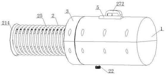
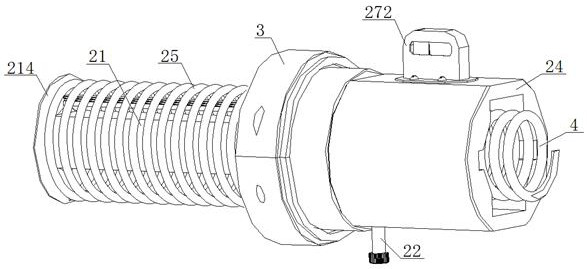
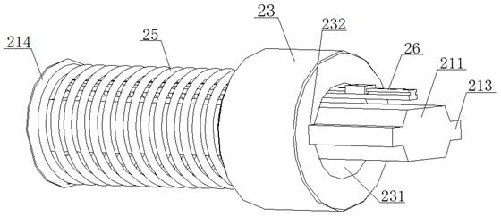
[0056] see Figure 1 to Figure 4 , a component deformation correction device, the correction device includes a housing 1 open at one end, a calibration verification assembly 2, an adjustment nut 3, a tension spring 4, a level 5, and the calibration verification assembly 2 is arranged on the housing 1 Inside, it includes a push rod 21, a follower set screw 22, an adjustment block 23, a follower sleeve 24, a spring 25, a guide rail 26, an indicator needle-dial assembly 27, and a sliding block 28. The indicator needle-dial assembly 27 includes The indicator needle 271, the dial 272 matched with the indicator needle 271, the adjustment nut 3, the ejector rod 21, the adjustment block 23, and the follower sleeve 24 are arranged coaxially with the housing 1, and the adjustment nut 3 is sleeved on the adjustment block 23 outside, the inner wall of the adjusting nut 3 is threadedly connected with the outer wall of the adjusting block 23, and the end faces of the adjusting nut 3 and the...

Embodiment 2

[0063] The difference with embodiment 1 is:

[0064] see Figure 5 , the correction device also includes a protective cover 6 with an open end, the inner wall of the open end of the protective cover 6 is threadedly connected with the outer wall of the adjustment nut 3, and one end of the guide rail 26, the B end 212, the spring 25, and the pressure plate 213 are all located at the protective cover. In the inside of the cover 6, the protective cover 6 can be removed during work.


PUM


Abstract

The invention discloses a part deformation correcting device. The part deformation correcting device comprises a shell with an opening in one end, a correcting and checking assembly arranged inside the shell and an adjusting nut arranged outside the correcting and checking assembly in a sleeving mode, one end of the correcting and checking assembly is fixedly connected with the inner wall of the shell through a tension spring, the other end of the correcting and checking assembly penetrates through the opening end of the shell and then extends out of the shell, the adjusting nut and the shell are coaxially arranged, one end of the adjusting nut is in running fit with the opening end of the shell, and the inner wall of the adjusting nut is in threaded connection with the outer wall of the correcting and checking assembly. During correction, the adjusting nut is rotated in the forward direction relative to the shell to enable the correcting and checking assembly to retract, then the correcting device is placed inside a to-be-corrected part, and then the adjusting nut is rotated in the reverse direction to enable the correcting and checking assembly to extend till the two ends of the correcting device abut against the two sides of the inner wall of the to-be-corrected part respectively, and finally, the adjusting nut continues to be reversely rotated until the size of the to-be-corrected part meets the design requirement, correction is completed, the structure is simple, operation is reliable, and correction efficiency is high.

Description

technical field [0001] The invention belongs to the technical field of part deformation correction, and in particular relates to a part deformation correction device and a use method thereof, which are suitable for improving the efficiency of part deformation correction and verification. Background technique [0002] During the manufacturing process of precision slender parts, especially welded parts with slender grooves or shells, due to the existence of welding internal stress and poor rigidity during processing, large deformations are likely to occur, and the size of the parts does not meet the design requirements. Therefore, it is necessary to perform multiple corrections on welded parts with slender grooves or shells. Generally, hammering, vise clamping, manual straightening or straightening on a press are required. Although the straightening function can be achieved, the correction There are still obvious shortcomings in terms of calibration efficiency and convenience....

Claims


Application Information

Patent Timeline
IPC IPC(8): B21D3/00B21C51/00
CPCB21D3/00B21C51/00
Inventor 程用泉
Owner WUHAN MARINE MACHINERY PLANT
Why Eureka
Try Eureka