
Winding former, winding device and winding method

A wire-winding die and wire-winding technology, which is applied in the direction of electromechanical devices, manufacturing motor generators, electrical components, etc., can solve problems such as coil damage, loose wires, and easy pull-off

Pending Publication Date: 2021-09-14
HITACHI ELEVATOR GUANGZHOU
View PDF0 Cites 0 Cited by
  • Summary
  • Abstract
  • Description
  • Claims
  • Application Information

AI Technical Summary

Problems solved by technology

However, self-adhesive hollow coils made with traditional winding dies generally have loose threads at the first and last coils. Loose or semi-loose threads are easy to pull off during subsequent operations, resulting in coil damage. Phenomenon

Method used


Image

  • Winding former, winding device and winding method
  • Winding former, winding device and winding method
  • Winding former, winding device and winding method

Examples


Embodiment Construction

[0030] In order to make the above objects, features and advantages of the present invention more comprehensible, specific implementations of the present invention will be described in detail below in conjunction with the accompanying drawings. In the following description, numerous specific details are set forth in order to provide a thorough understanding of the present invention. However, the present invention can be implemented in many other ways different from those described here, and those skilled in the art can make similar improvements without departing from the connotation of the present invention, so the present invention is not limited by the specific embodiments disclosed below.

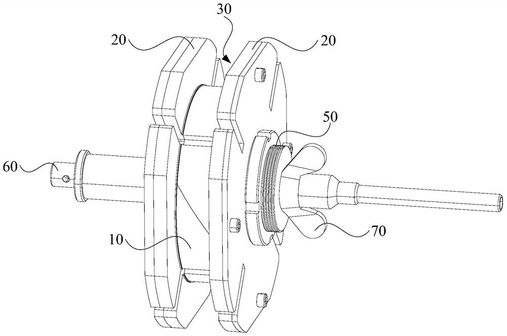
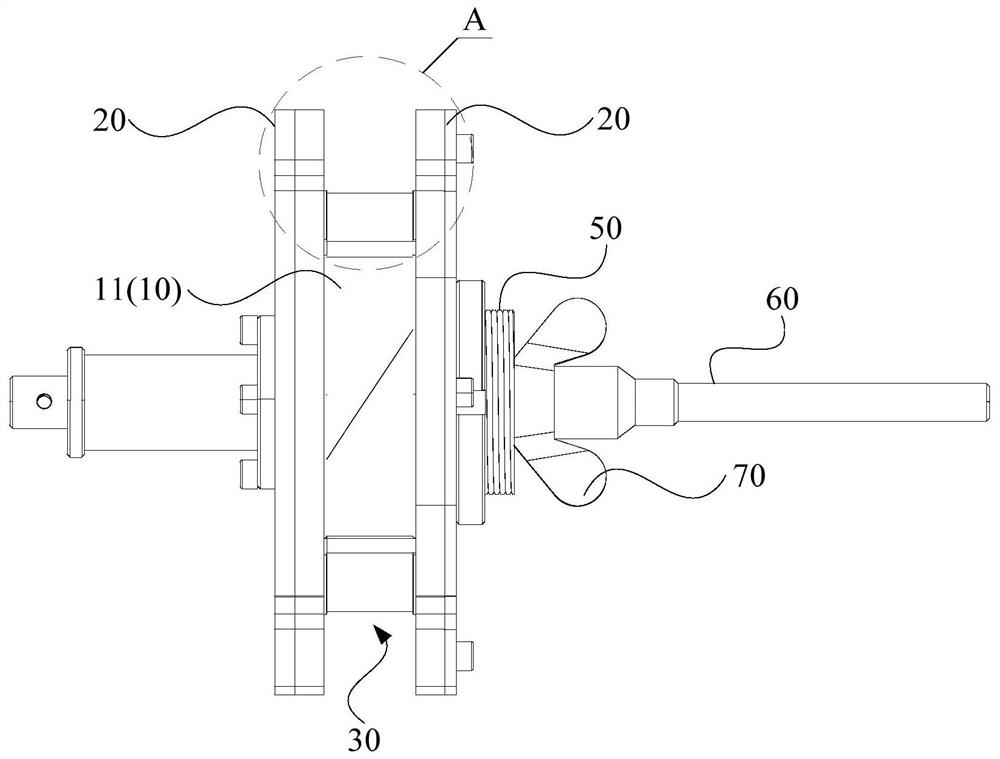
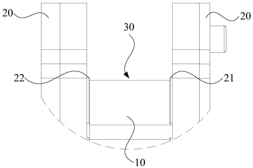
[0031] refer to figure 1 , image 3 and Figure 4 , The wire winding die provided by an embodiment of the present invention includes a core 10 and at least two side plates 20, and at least two side plates 20 are arranged opposite to each other. The mold core 10 is disposed between at l...


PUM


Abstract

The invention relates to a winding former, a winding device and a winding method. The winding former comprises a mold core and two side plates which are oppositely arranged. The mold core is arranged between the two side plates and a winding area is defined by the mold core and the two side plates. A first protruding part and a second protruding part are arranged on the two sides of the winding area respectively, and the first protruding part is used for bonding the second-layer first-circle winding and the winding located on the second layer and adjacent to the second-layer first-circle winding to the first-layer tail-circle winding. The second protruding part is used for enabling the second-layer tail coil winding and the winding located on the second layer and adjacent to the second-layer tail coil winding to be bonded to the first-layer first coil winding. Thus, the bonding area of the first-layer first-circle winding and the first-layer tail-circle winding is increased, the bonding force is improved, the phenomenon of coil loosening is effectively avoided, and the product quality is guaranteed.

Description

technical field [0001] The invention relates to the technical field of motors, in particular to a winding die, a winding device and a winding method. Background technique [0002] The hollow coil made of self-adhesive enamelled round copper wire is made by winding the self-adhesive enameled round copper wire on the winding die. stick. However, self-adhesive hollow coils made with traditional winding dies generally have loose threads at the first and last coils, and the loose or semi-loose threads are easy to pull off during subsequent operations, resulting in damage to the coils Phenomenon. Contents of the invention [0003] Based on this, it is necessary to provide a winding die, a winding device and a winding method, which can prevent the coil from loosening. [0004] A winding die, comprising: [0005] at least two side panels, at least two of said side panels are positioned opposite each other; and [0006] The mold core is arranged between at least two of the sid...

Claims


Application Information

Patent Timeline
Patent Type & Authority Applications(China)
IPC IPC(8): H02K15/04H02K15/00
CPCH02K15/0464H02K15/0081
Inventor 王宏方天兵禹婷华
Owner HITACHI ELEVATOR GUANGZHOU
Learn More