A motor prefabricated winding embedding equipment

A winding and equipment technology, applied in the field of motor prefabricated winding embedding equipment, can solve the problems of scattered ends of prefabricated windings, scattered prefabricated windings, uneven ends of prefabricated windings, etc.

Active Publication Date: 2021-10-29
佛山市晶本电机有限公司
View PDF9 Cites 0 Cited by
  • Summary
  • Abstract
  • Description
  • Claims
  • Application Information

AI Technical Summary

Problems solved by technology

[0005] In order to overcome the fact that when the coil is wound into a prefabricated winding, the two sets of wire ends of the wire are scattered. When the prefabricated winding is pressed into the motor, the scattered wire ends will be scraped off at the edge of the motor stator, and the loose prefabricated winding When pressing into the motor stator, the two ends of the prefabricated winding are not flat, and the parts of the prefabricated windings exposed on both sides of the motor stator are scattered. It is difficult to arrange the wire harness of the exposed part of the prefabricated windings. This application aims to solve the problem of the wire ends of the prefabricated windings. Scattered and loose windings are embedded in the motor stator and the technical problems are uneven at both ends

Method used


Image

  • A motor prefabricated winding embedding equipment
  • A motor prefabricated winding embedding equipment
  • A motor prefabricated winding embedding equipment

Examples


Embodiment 1

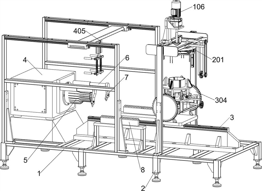
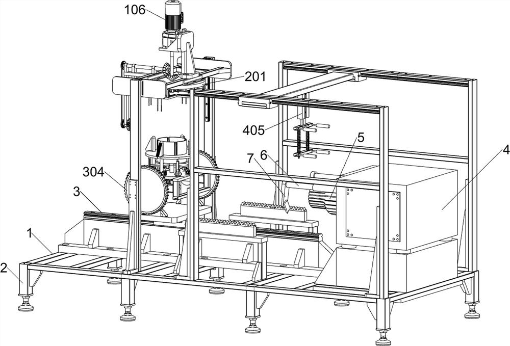
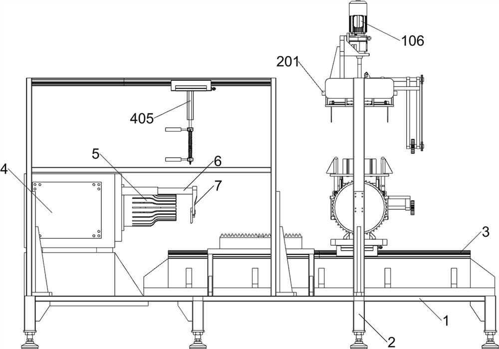
[0040] A motor prefabricated winding embedding device, according to Figure 1-3 As shown, it includes a chassis 1, a support 2, a first electric slide rail 3, a press 4, a support sleeve 5, a rotating telescopic rod 6, a baffle 7, a rack 8, a first support 101, a second Electric slide rail 102, fourth electric slider 103, sliding frame 104, drive unit, carding unit, material sorting unit and assembly unit; bottom frame 1 is fixedly connected with support 2; Electric slide rail 3; a press 4 is fixedly connected to the upper left part of the bottom frame 1; a group of racks 8 are fixedly connected to the front and rear of the upper middle part of the bottom frame 1; a support sleeve 5 is fixedly connected to the right middle part of the press machine 4; A group of rotating telescopic rods 6 are fixedly connected to the front and rear parts on the right; two groups of baffle plates 7 are fixedly connected to the right ends of the two groups of rotating telescopic rods 6; the uppe...

Embodiment 2

[0051] according to figure 1 with Figure 14-15 As shown, an assembly unit is also included, and the assembly unit includes a third support member 401, a third electric slide rail 402, a sixth electric slide block 403, a connecting plate 404, a second electric actuator 405, a first support plate 406, The first clamping piece 407, the elastic piece 408, the second supporting plate 409 and the second clamping piece 4010; a set of third supporting pieces 401 are fixedly connected to the front and rear of the upper middle left part of the chassis 1; two sets of third supporting pieces 401 A set of third electric slide rails 402 is fixedly connected to the upper top; a sixth electric slider 403 is slidably connected to the bottom of the two sets of third electric slide rails 402; a connecting plate 404 is fixedly connected between the two sets of sixth electric slides 403; The middle part below the connection plate 404 is fixedly connected with the second electric actuator 405; th...


PUM


Abstract

The present application relates to the field of motors, in particular to a device for embedding prefabricated windings of motors. The technical problem of the present application is: the wire ends of the prefabricated winding are scattered and the two ends of the loose winding embedded in the motor stator are uneven. The technical implementation of the present application is: a motor prefabricated winding embedding device, including a drive unit, a carding unit, a material sorting unit and an assembly unit; the carding unit is internally connected above the drive unit. This application realizes the combing of the wire ends of the prefabricated windings to prevent the wire ends from being stuck when the windings are embedded in the motor stator frame, and the outward expansion tension of multiple sets of prefabricated windings, so that the two ends of the prefabricated windings are flat when embedded in the motor , during the tensioning process, the prefabricated winding is flattened to avoid the winding being stuck during the transfer process, which can effectively improve the production efficiency of the prefabricated winding embedded in the motor.

Description

technical field [0001] The present application relates to the field of motors, in particular to a device for embedding prefabricated windings of motors. Background technique [0002] As the power source of electrical appliances and various machinery, the motor is a device that realizes the conversion of electric energy according to the law of electromagnetic induction. Through the change of the electric field, the coil moves in the electric field. [0003] At present, the wires are usually pre-wound into prefabricated windings, and then combined with the motor. However, when the coils are wound into prefabricated windings, the two sets of wire ends of the wires are scattered. When the prefabricated windings are pressed into the motor, the scattered wire ends The wires will be scraped off at the edge of the motor stator, and when the loose prefabricated windings are pressed into the motor stator, the ends of the prefabricated windings will be uneven, and the exposed parts of ...

Claims


Application Information

Patent Timeline
Patent Type & Authority Patents(China)
IPC IPC(8): H02K15/04H02K15/06
CPCH02K15/04H02K15/06
Inventor 陈咏娜胡淅苏坤
Owner 佛山市晶本电机有限公司
Why Eureka
Try Eureka