Backflow assembly of ball screw

A ball screw and assembly technology, applied in the direction of transmission, belt/chain/gear, mechanical equipment, etc., can solve the problems of shortened travel of recirculating ball screw, extrusion of beads, and many processes of return end cap

Active Publication Date: 2021-09-17
HIWIN TECH
View PDF18 Cites 0 Cited by
  • Summary
  • Abstract
  • Description
  • Claims
  • Application Information

AI Technical Summary

Problems solved by technology

[0003] After the ball screw is used for a long time, wear will occur, which in turn will lead to the problem that the rolling element flows unsmoothly. The situation of bead squeezing is caused, and then pressure is applied to the return end cover in the return flow channel. Once the pressure is too large, the return end cover made of plastic material will be damaged, causing the rolling parts to flow out, and then the return end cover will be damaged. The screw shaft and the nut seat cannot operate in a normal manner and must be shut down for maintenance. On the other hand, when the screw shaft is of the type extending up and down, the outflow of the rolling elements will cause the nut seat to be unrestricted. Dropping along the screw shaft will not only damage the recirculating ball screw further, but also damage the surrounding machines or other materials
[0004] Another type of recirculating ball screw will install a metal safety cover on the outside of the return end cover, so that when the return end cover is damaged, the rolling parts will not flow out. However, this method will cause the circulation The stroke of the type ball screw is shortened, and there are many procedures for replacing the return end cover, which has the problem of inconvenient maintenance.

Method used


Image

  • Backflow assembly of ball screw
  • Backflow assembly of ball screw
  • Backflow assembly of ball screw

Examples


Embodiment Construction

[0028] The present invention will be described in detail below in conjunction with the accompanying drawings and embodiments.

[0029] For convenience of description, in the following embodiments, the same components are denoted by the same reference numerals.

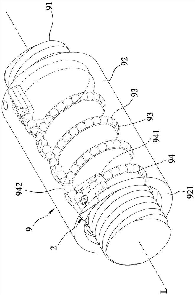
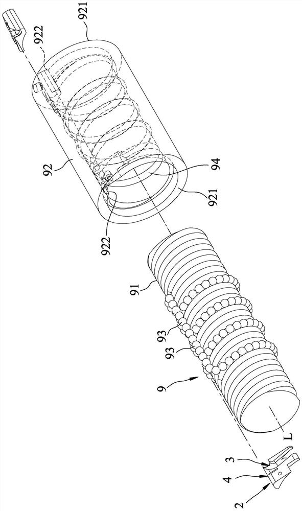
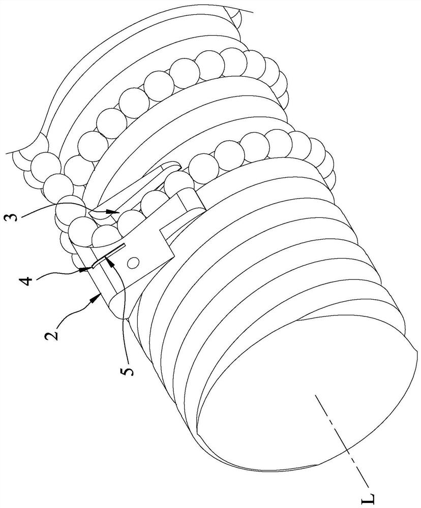
[0030] refer to figure 1 , 2 , 3. The first embodiment of the return assembly of the ball screw of the present invention is applied to the ball screw 9, and the ball screw 9 includes a screw shaft 91 extending along an axis L, and a nut seat 92 surrounding the screw shaft 91 , a plurality of rolling elements 93 that can be cyclically arranged between the screw shaft 91 and the nut seat 92, and a plurality of rolling grooves formed inside the nut seat 92 for the cyclic rolling of the rolling elements 93 94. In this embodiment, the rolling element 93 is a ball, and it can also be a roller or other equivalent elements in other embodiments.

[0031] The nut seat 92 has two oppositely disposed end faces 921 perpendicula...


PUM


Abstract

The invention discloses a backflow assembly of a ball screw. The ball screw comprises a nut seat, multiple rolling pieces and a rolling groove which is formed in the inner side of the nut seat to allow the rolling pieces to roll circularly. The rolling groove is provided with an outflow section and an inflow section. The backflow assembly comprises a backflow piece, a rotation groove, a mounting groove and a sensing module, the backflow piece is arranged on the nut seat, the rotation groove penetrates through the backflow piece, and the two opposite ends of the rotation groove correspond to the outflow section and the inflow section correspondingly. The rotation groove comprises a rotation section which communicates with the outflow section and rotates around a reference point and a leading-out section which is connected with the rotation section and the inflow section. The mounting groove is formed in the backflow piece and relatively located on the outer side of the rotation section, the sensing module is arranged in the mounting groove and can output a warning signal when the backflow piece bears force to deform and the two opposite sides are pressed, and a safety protection effect can be achieved.

Description

technical field [0001] The invention relates to a ball screw, in particular to a return assembly of the ball screw. Background technique [0002] An existing recirculating ball screw comprises a screw shaft, a nut seat sheathed on the screw shaft, two return end caps respectively arranged at two opposite ends of the nut seat, and a plurality of return caps which can be mounted on the nut seat. The rolling element that circulates between the seat and the return end cover. [0003] After the ball screw is used for a long time, wear will occur, which in turn will lead to the problem that the rolling element flows unsmoothly. The situation of bead squeezing is caused, and then pressure is applied to the return end cover in the return flow channel. Once the pressure is too large, the return end cover made of plastic material will be damaged, causing the rolling parts to flow out, and then the return end cover will be damaged. The screw shaft and the nut seat cannot operate in a...

Claims


Application Information

Patent Timeline
Patent Type & Authority Applications(China)
IPC IPC(8): F16H25/22
CPCF16H25/2214F16H25/2454
Inventor 陈鼎元林育新魏照恩
Owner HIWIN TECH
Why Eureka
Try Eureka