Auxiliary Tooling for Cylindrical Roller Bearing Inspection

A technology of cylindrical roller bearings and auxiliary tooling, which is applied in the direction of mechanical bearing testing, measuring devices, and testing of mechanical components, and can solve the problems of high processing costs and low adaptability of supporting tooling, so as to reduce processing costs and types The effect of quantity and convenient operation

Active Publication Date: 2022-04-12
C&U CO LTD +1
View PDF0 Cites 0 Cited by
  • Summary
  • Abstract
  • Description
  • Claims
  • Application Information

AI Technical Summary

Problems solved by technology

[0005] Aiming at the deficiencies of the prior art, the present invention provides an auxiliary tooling for the inspection of cylindrical roller bearings with no ribs on the inner ring, which can be adapted to use in different sizes and keep the inner ring running normally during the test, solving the problems in the prior art. The problem of low adaptability of supporting tooling and high processing cost

Method used


Image

  • Auxiliary Tooling for Cylindrical Roller Bearing Inspection
  • Auxiliary Tooling for Cylindrical Roller Bearing Inspection
  • Auxiliary Tooling for Cylindrical Roller Bearing Inspection

Examples


Embodiment 1

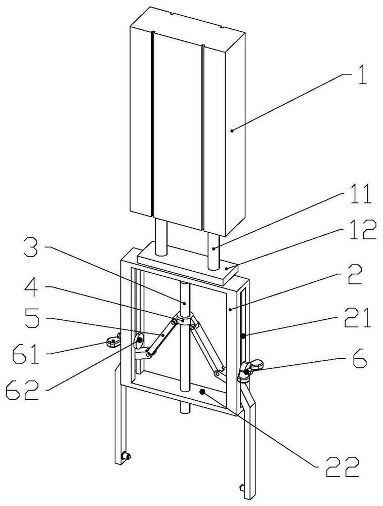
[0030] Embodiment 1 This embodiment provides a cylindrical roller bearing detection auxiliary tool, including a loading mechanism, a main frame body 2, a threaded rod 3 and a swing clamping assembly 5, wherein the swing clamping assembly 5 includes a pair of symmetrical connections and threads The connecting rod 51 and the fixed claw 52 on the rod 3. Such as figure 1 As shown, in the present embodiment, the loading mechanism adopts the cylinder 1, and the cylinder 1 is provided with an air chamber and a piston that displaces following the volume change of the air chamber, and at least two parallel piston rods 11 are connected to the piston. In this embodiment, , There are two piston rods 11. One end of the piston rod 11 is fixedly connected to the piston, and the other end of the piston rod 11 is connected to a top plate 12 , and is detachably and fixedly connected to the top of the main frame body 2 through the top plate 12 . to combine Figure 5 As shown, the main frame b...

Embodiment 2

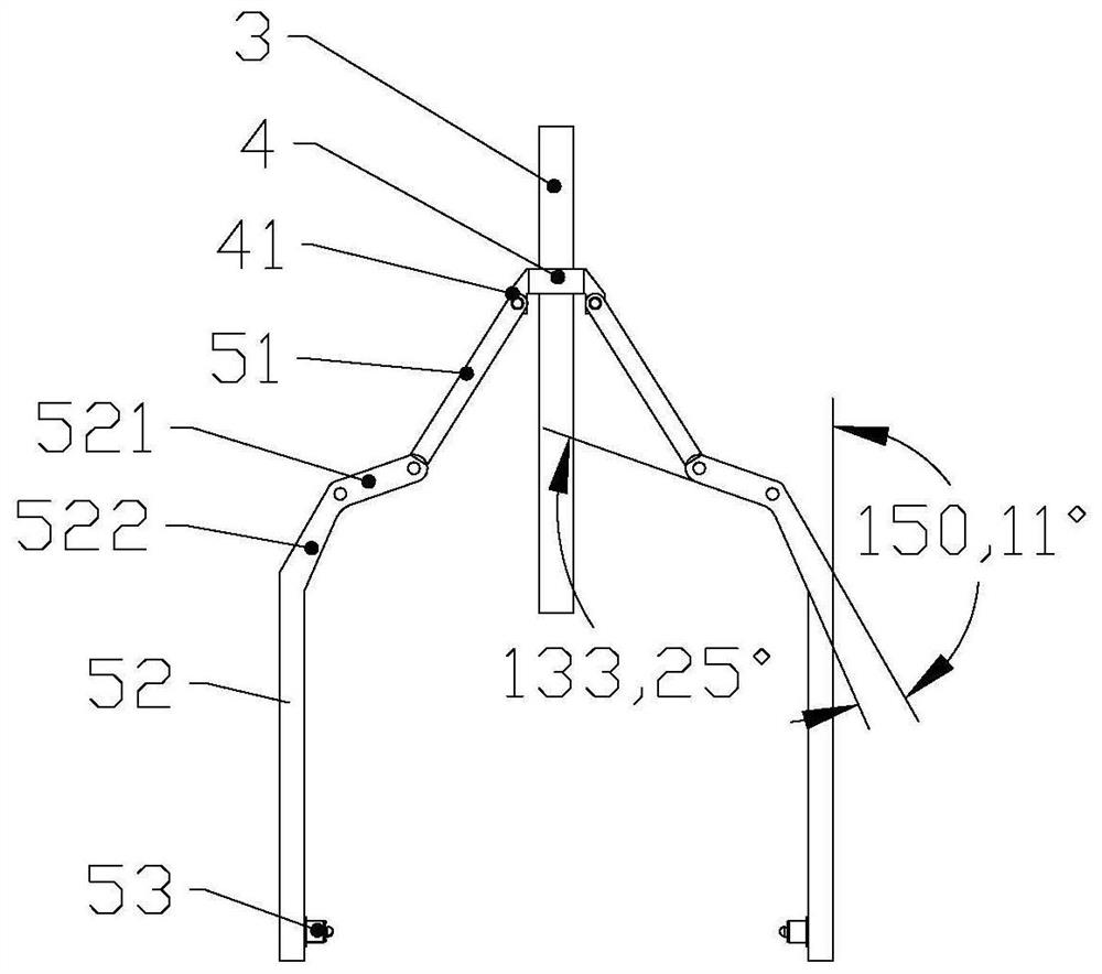
[0035] Embodiment 2 The difference between this embodiment and Embodiment 1 is that: the bending rod is an arc-shaped bending structure, and the arc angle corresponding to the arc-shaped bending structure is 133-136°. Compared with the double-short straight rod structure in Embodiment 1, the structure of this embodiment may be easier to process, and there are relatively few swing bumps during the swinging process of the fixed claw 52, ​​but its controllability is lower than that in Embodiment 1. double straight rod structure.

Embodiment 3

[0036] Embodiment 3 The difference between this embodiment and Embodiment 1 is that in this embodiment, the straight rod includes a rod one and a rod two, wherein the rod one and the rod two are detachably and fixedly connected, such as threaded connection, clamping or socket. One end of the first rod is hinged with the connecting rod 51, and the other end is fixedly connected with the second rod, and the other end of the second rod is used as the bottom end of the straight rod, on which the fixed head 532 described in the first embodiment is arranged.

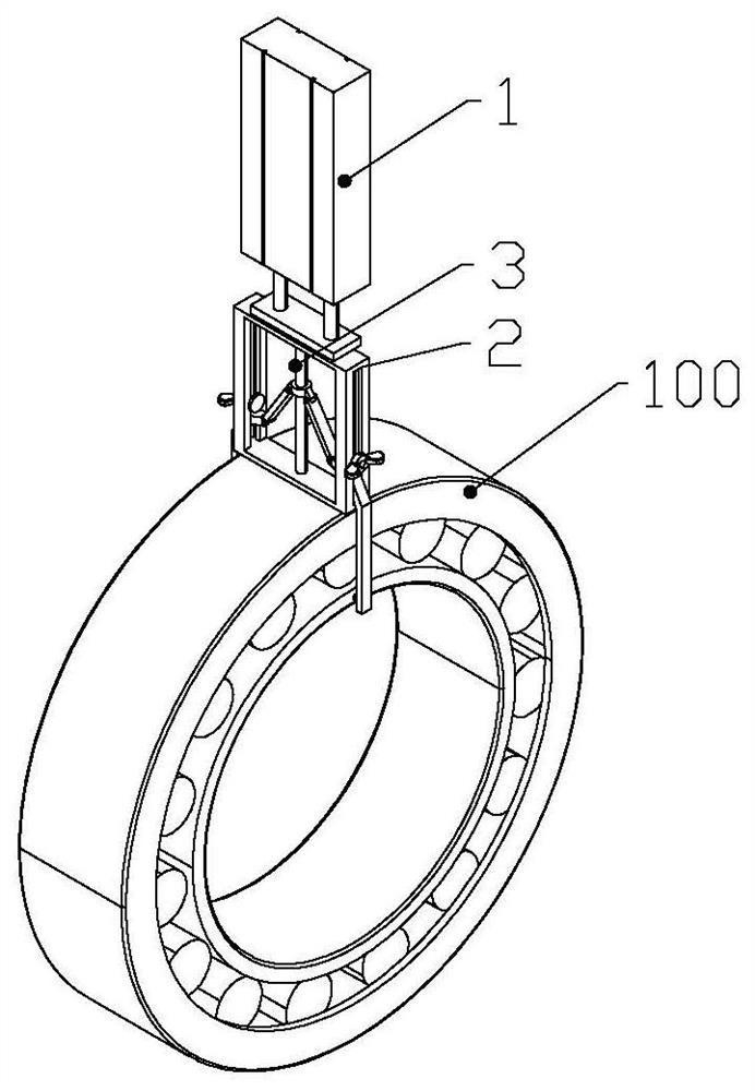
[0037] In summary, the present invention provides a simple structure and strong versatility to limit the axial displacement of the bearing inner ring 101 of the cylindrical roller bearing without inner ring rib by clamping on both sides, effectively avoiding the The situation that the bearing inner ring 101 disengages occurs. Through the control of the loading mechanism, the running stability of the bearing inner ring 101 can...


PUM


Abstract

The invention provides an auxiliary tool for detecting a cylindrical roller bearing, belonging to the technical field of bearing detection, comprising a loading mechanism, a main frame body, a threaded rod, a connecting rod and a fixing claw. , the loading mechanism is fixed with the top rod, the threaded rod is vertically penetrated on the bottom rod, and the side rod is provided with a through groove. The threaded rod is threadedly connected with a threaded sleeve. One end of the connecting rod is hinged with the threaded sleeve, and the other end is hinged with one end of the fixing claw; The ends of the walls are provided with fixed heads. A limit component for restricting the upward sliding of the curved rod is detachably connected to the through groove. The invention has simple structure and strong versatility to limit the axial displacement of the bearing inner ring of the cylindrical roller bearing without inner ring ribs by clamping on both sides, thereby effectively avoiding the occurrence of the separation of the bearing inner ring under measurement conditions.

Description

technical field [0001] The invention relates to the technical field of bearing auxiliary instruments, in particular to an auxiliary tooling for detecting cylindrical roller bearings with no ribs on the inner ring. Background technique [0002] In the previous inspection process, the cylindrical roller bearings without inner ring ribs could not withstand the axial load during the vibration noise measurement due to the lack of inner ring ribs. The phenomenon of detaching from the mandrel causes the test to be aborted. [0003] In order to avoid the occurrence of the above phenomenon, in the prior art, an upper and lower threaded hole is usually processed in the center of the mandrel, and then the inner ring is axially locked by the matching tooling. Since the size of the matching tooling needs to be compatible with the bearing, there are many types and quantities of supporting tooling in this fixing method, and there is a greater pressure on processing costs. [0004] Based ...

Claims


Application Information

Patent Timeline
Patent Type & Authority Patents(China)
IPC IPC(8): G01M13/04G01M13/045
CPCG01M13/04
Inventor 焦鹏
Owner C&U CO LTD
Why Eureka
Try Eureka