
Wiring terminal with heat dissipation cavity

A terminal and heat dissipation technology, applied in the field of power supply connectors, can solve the problems of easy heat generation, hidden dangers, external power cables and wires, etc., to achieve the effect of good heat dissipation and improved insulation safety

Pending Publication Date: 2021-09-17
JIANGXI HANGTONG ELECTRIC TECH CO LTD
View PDF0 Cites 0 Cited by
  • Summary
  • Abstract
  • Description
  • Claims
  • Application Information

AI Technical Summary

Problems solved by technology

Any device needs power supply, although part of it can be realized by batteries, wireless charging, etc., but more needs to be provided by external power cables and wires, such as most 1500V, 380V industrial electricity and 220V, 110V Household electricity, this voltage is dangerous to the human body, it must be handled by a professional electrician during installation, maintenance, and replacement
[0003] Due to the different ways of taking power from components and electrical equipment, there are wires of various specifications, and wires of various specifications must be connected together to conduct electricity at the same time. After the equipment is in operation, the large current generated by the wires will easily generate heat. Conducted to the terminal, so that the terminal is at high temperature for a long time, which will cause safety hazards and shorten the service life of the terminal. Therefore, a through-wall terminal with a heat dissipation cavity is urgently needed to solve this problem

Method used


Image

  • Wiring terminal with heat dissipation cavity
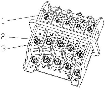
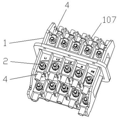
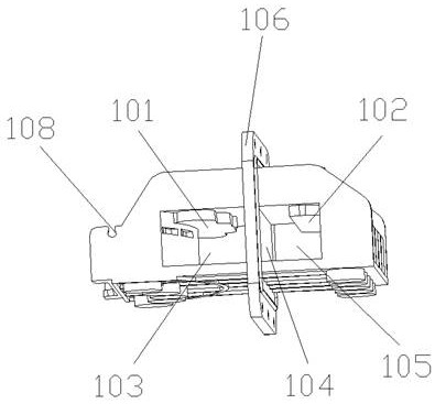
  • Wiring terminal with heat dissipation cavity
  • Wiring terminal with heat dissipation cavity

Examples


Embodiment Construction

[0022] The technical solutions in the embodiments of the present invention will be clearly and completely described below in conjunction with the accompanying drawings in the embodiments of the present invention. Obviously, the described embodiments are only some of the embodiments of the present invention, not all of them. Based on The embodiments of the present invention and all other embodiments obtained by persons of ordinary skill in the art without making creative efforts belong to the protection scope of the present invention. as attached figure 1 to attach Figure 4 Shown:

[0023] This embodiment provides a connection terminal with a heat dissipation cavity, including an insulating body 1, a bolt group 2 and a conductive sheet 3, and is characterized in that the insulating body 1 is provided with a plurality of conductive sheets 3 and bolt groups 2, and the conductive sheet 3 The bolt group 2 is embedded in the insulating body 1, and the insulating body 1 is provide...


PUM


Abstract

The invention relates to the technical field of connectors, in particular to a wiring terminal with a heat dissipation cavity. Thewiring terminal comprises an insulating body, bolt groups and conducting strips, wherein the insulating body is provided with a plurality of conducting strips and bolt groups, the conducting strips and the bolt groups are embedded in the insulating body, the insulating body is provided with the heat dissipation cavities and bolt group fixing parts, and a large cavity is arranged in the middle of the terminal, so that contact area with air is increased, and a good heat dissipation function can be achieved. A cavity partition wall is arranged between the heat dissipation cavities, so that the interior and the exterior of the terminal have a good waterproof effect after the terminal is installed on an equipment shell; and the front edge of the insulating body is provided with a limiting step for limiting the rotation angle of the wiring nose, so that the wiring nose can be prevented from rotating and getting close to each other to cause short circuit.

Description

technical field [0001] The invention relates to the technical field of power supply connectors, in particular to a connection terminal with a heat dissipation cavity. Background technique [0002] With the development of hardware intelligence and the Internet of Things, various components and electrical equipment are widely used in industrial production, communication, family life and other fields. Any device needs power supply, although part of it can be realized by batteries, wireless charging, etc., but more needs to be provided by external power cables and wires, such as most 1500V, 380V industrial electricity and 220V, 110V Household electricity, this voltage is a dangerous voltage for the human body, and it must be handled by professional electricians during installation, maintenance, and replacement. [0003] Due to the different ways of taking power from components and electrical equipment, there are wires of various specifications, and wires of various specificatio...

Claims


Application Information

Patent Timeline
Patent Type & Authority Applications(China)
IPC IPC(8): H01R13/40H01R4/30H01R9/00
CPCH01R13/40H01R4/30H01R9/00
Inventor 龚义祥刘燕青刘建
Owner JIANGXI HANGTONG ELECTRIC TECH CO LTD
Learn More