
A drive interface system for single-coil relays that supports both active and standby drives

A technology for driving interfaces and relays, applied in information technology support systems, circuit devices, electrical components, etc., can solve the problems of unavailable state of safety drive unit and reduce system availability, and achieve maintainability, small size, flexibility and reliability The effect of scalability

Active Publication Date: 2022-07-26
CASCO SIGNAL
View PDF12 Cites 0 Cited by
  • Summary
  • Abstract
  • Description
  • Claims
  • Application Information

AI Technical Summary

Problems solved by technology

During operation, the safety drive unit needs to periodically change the level of the output port and read back the level information of the port for self-testing of its own circuit. When two redundant safety drive units drive a single-coil relay together, the main and backup systems The output port will be connected to the same group of contacts, and the self-test result will be affected by the output level of the corresponding port, which will eventually cause one of the safety drive units to enter an unavailable state due to self-test failure, reducing system availability

Method used


Image

  • A drive interface system for single-coil relays that supports both active and standby drives
  • A drive interface system for single-coil relays that supports both active and standby drives
  • A drive interface system for single-coil relays that supports both active and standby drives

Examples


Embodiment Construction

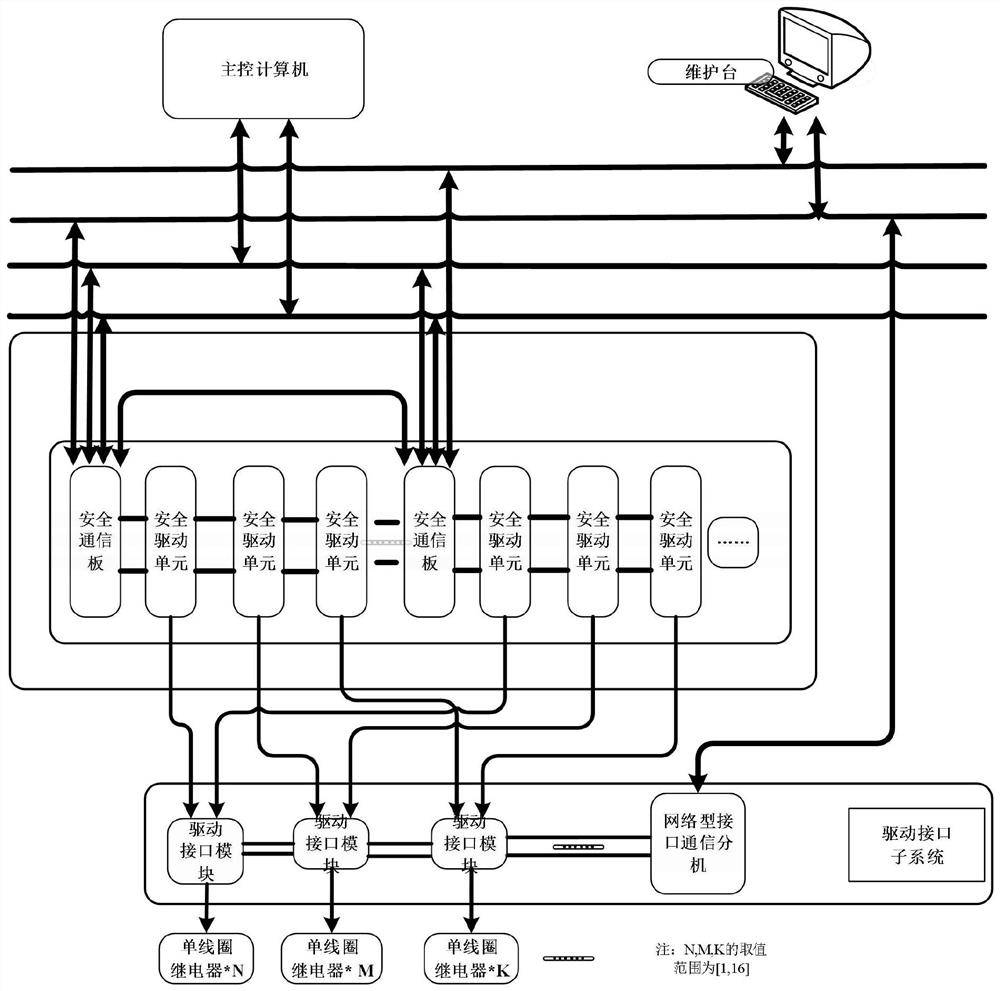
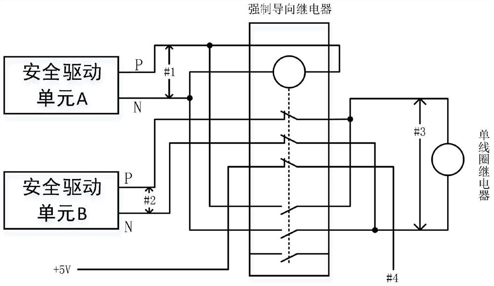
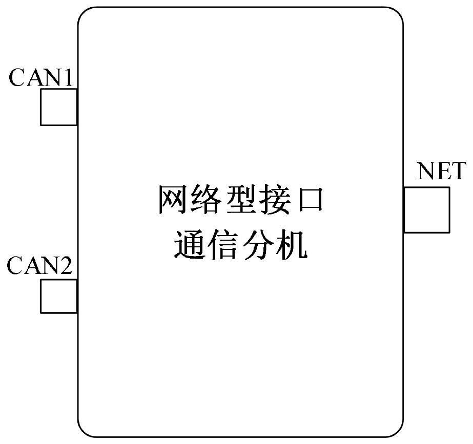
[0024] Attached to the following Figure 1-5 The driving interface system of the single-coil relay supporting the main-standby co-driving proposed by the present invention will be further described in detail with the specific embodiments. The advantages and features of the present invention will become more apparent from the following description. It should be noted that the accompanying drawings are in a very simplified form and all use inaccurate scales, and are only used to facilitate and clearly assist the purpose of explaining the embodiments of the present invention. For the purpose, features and advantages of the present invention to be more clearly understood, please refer to the accompanying drawings. It should be noted that the structures, proportions, sizes, etc. shown in the drawings in this specification are only used to cooperate with the contents disclosed in the specification, so as to be understood and read by those who are familiar with the technology, and a...


PUM


Abstract

The present invention provides a drive interface system for a single-coil relay that supports both main and standby drives, so that two mutually redundant safety drive units can drive the single-coil relay through the drive interface system, including a drive interface module; a drive interface module The input end of the main safety drive unit and the output end of the backup safety drive unit are connected to the output end of the drive interface module, and the output end of the drive interface module is connected to the single-coil relay. The main safety drive unit and the backup safety drive unit are redundant with each other; the drive interface module includes mandatory guidance Relay, one group of outputs of the main safety drive unit is connected to the coil of the forced guide relay, the other group of outputs is connected to the normally open contact of the forced guide relay, and the output of the backup safety drive unit is connected to the normally closed contact of the forced guide relay; in the forced guide The output terminal of the relay connects the normally open contact and the normally closed contact in parallel to the single coil relay. This system makes the self-checks of the main and backup safety drive units not affect each other.

Description

technical field [0001] The invention relates to the technical field of rail transit circuits, in particular to a drive interface system for a single-coil relay that supports both active and standby drives. Background technique [0002] In domestic rail traffic signal systems, double-coil relays are usually used to build rail safety circuits, while foreign markets and some domestic applications use single-coil relays to build safety circuits due to cost and other factors. The safety drive unit of the rail transit system is used to execute the control command of the interlocking machine. In order to improve the system availability, two redundant safety drive units are usually used to output 24V voltage to drive the two coils of the double-coil relay. Some safety drive units are also mainly designed for this scenario. During operation, the safety drive unit needs to periodically change the level of the output port and read back the level information of the port for self-checki...

Claims


Application Information

Patent Timeline
Patent Type & Authority Patents(China)
IPC IPC(8): H02J13/00B61L1/18
CPCH02J13/00002H02J13/00016H02J13/00036B61L1/18Y02E60/00Y04S40/124
Inventor 杨硕郑晓杰杨春王国星王鹤翔叶瑞源许婧许西鹏
Owner CASCO SIGNAL
Learn More