Anti-interference antenna with high isolation of receiving and transmitting channels

A high-isolation, transceiver channel technology, applied in the direction of antenna, antenna coupling, antenna array, etc., can solve the problems of anti-jamming antenna, loss of lock, loss of positioning function of satellite navigation equipment, etc., to achieve carrier loss of lock and cycle slip reduction , Stable work, correct and reliable processing results

Pending Publication Date: 2021-09-21
西安合众思壮防务科技有限责任公司
View PDF0 Cites 0 Cited by
  • Summary
  • Abstract
  • Description
  • Claims
  • Application Information

AI Technical Summary

Problems solved by technology

At present, with the opening and operation of the Beidou-3 satellite navigation system service, the navigation receiver transmits and receives more frequency points and a wider frequency band, which leads to the influence between the channels in the anti-jamming antenna and has a great impact on the performance of the navigation equipment. big impact
[0003] In the Beidou-3 navigation receiver, the transmitting frequency points are Lf1~Lf5, and the frequency covers the range of 1610MHz~1680MHz. The receiving frequency point closest to the transmitting frequency is B1 frequency point 1575.42MHz, and the transmitting power is about 10W, that is, 40dBm. The difference between the B1 signal landing power -133dBm is 173dBm. If no effective measures are taken, the B1 frequency point will definitely lose lock when the L signal is launched, which will directly cause the satellite navigation equipment to lose its positioning function.

Method used


Image

  • Anti-interference antenna with high isolation of receiving and transmitting channels
  • Anti-interference antenna with high isolation of receiving and transmitting channels
  • Anti-interference antenna with high isolation of receiving and transmitting channels

Examples


Embodiment Construction

[0018] The present invention will be further elaborated below in conjunction with the accompanying drawings and specific embodiments.

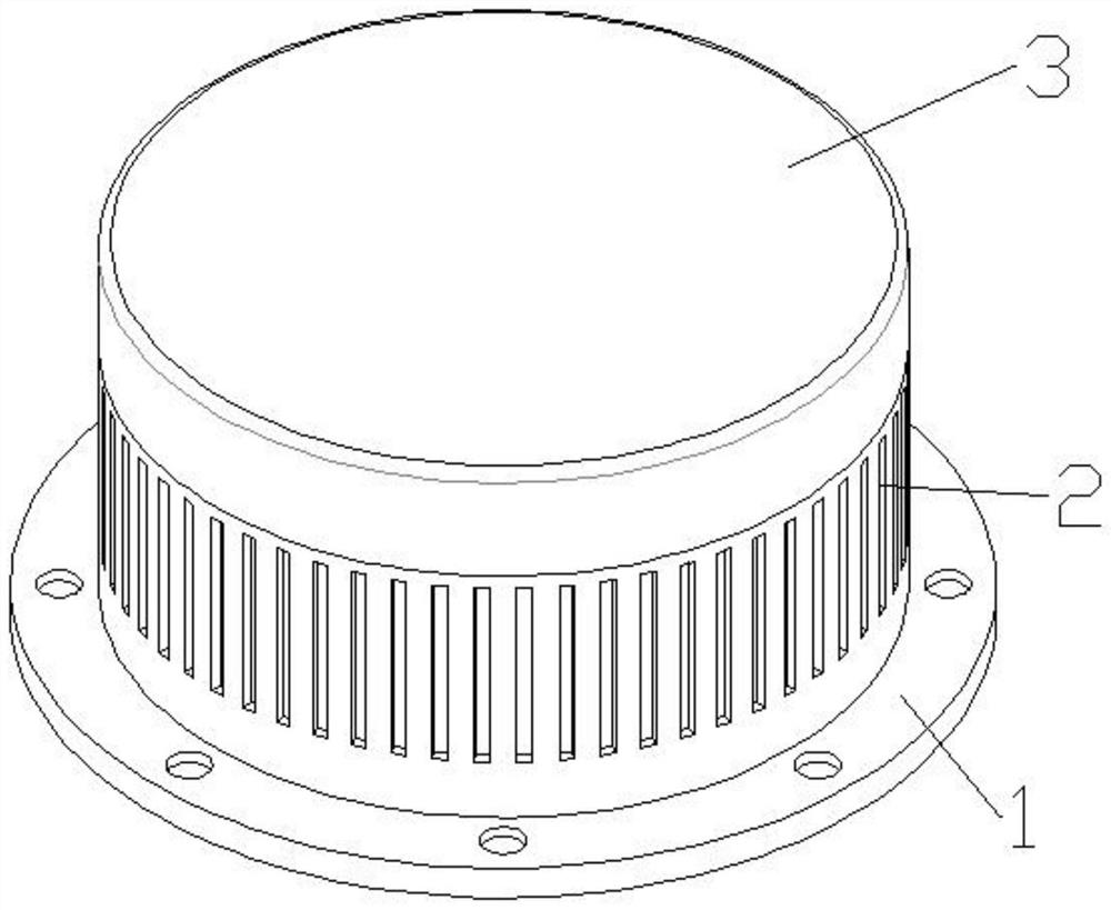
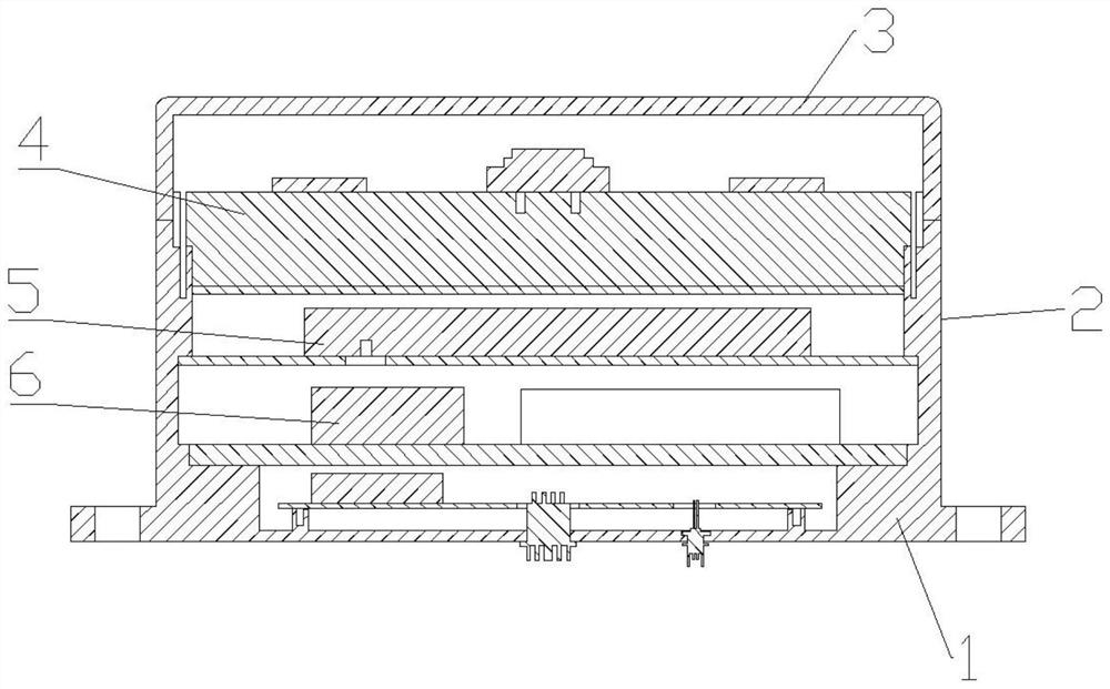
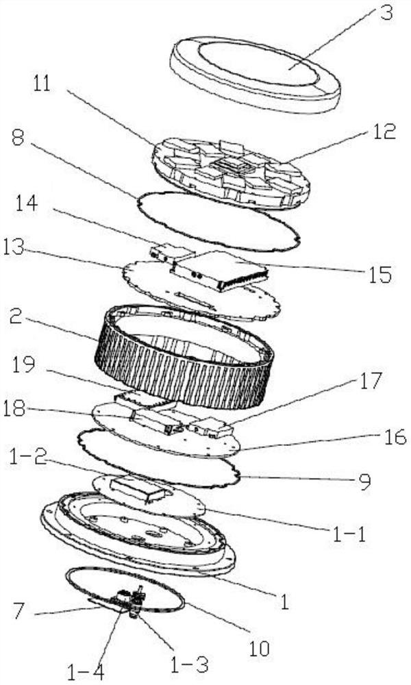
[0019] Such as Figure 1-3 As shown in the figure, an anti-jamming antenna with high isolation of transmitting and receiving channels includes a base 1, a power supply PCB 1-1, a power supply module 1-2, a TNC radio frequency seat 1-3, an aviation socket 1-4, an antenna cavity 2, and a radome 3. Antenna layer 4, anti-interference layer 5, power amplifier layer 6, nameplate 7, antenna sealing ring 8, cavity sealing ring 9, base sealing ring 10, the base 1 is fixedly installed with a power supply PCB1-1 inside, and the power supply A power module 1-2 is installed on the top of the PCB 1-1, and a TNC radio frequency seat 1-3 and an aviation socket 1-4 are inserted at the bottom. Antenna cavity 2 is installed on the top of the base 1, and the top of the antenna cavity 2 is buckled. Connected with a radome 3, the antenna cavity 2 is sequentially i...


PUM


Abstract

The invention discloses an anti-interference antenna with high isolation of receiving and transmitting channels. The antenna comprises a base, a power supply PCB, a power supply module, a TNC radio frequency seat, an aviation socket, an antenna cavity, an antenna cover, an antenna layer, an anti-interference layer, a power amplifier layer, a nameplate, an antenna sealing ring, a cavity sealing ring and a base sealing ring, the power supply PCB is fixedly mounted in the base 1, and the power supply module is mounted at the top of the power supply PCB; and a TNC radio frequency seat and an aviation socket are inserted into the bottom of the base, an antenna cavity is formed in the top of the base, an antenna cover is buckled to the top of the antenna cavity, and an antenna layer, an anti-interference layer and a power amplifier layer are sequentially installed in the antenna cavity from top to bottom. When the L signal is transmitted, the B1I signal keeps continuous tracking, the carrier loss of lock and cycle slip under the interference environment are obviously reduced, and the long-term operation and work are stable through test verification under the darkroom environment and the actual weather condition.

Description

technical field [0001] The present invention relates to an anti-jamming antenna, in particular to an anti-jamming antenna with high isolation of transceiver channels. Background technique [0002] In satellite navigation and positioning equipment, the anti-jamming antenna is the key equipment to improve the navigation performance of satellite navigation equipment, improve the availability of satellite navigation and positioning, and improve environmental adaptability. At present, with the opening and operation of the Beidou-3 satellite navigation system service, the navigation receiver transmits and receives more frequency points and a wider frequency band, which leads to the influence between the channels in the anti-jamming antenna and has a great impact on the performance of the navigation equipment. big impact. [0003] In the Beidou-3 navigation receiver, the transmitting frequency points are Lf1~Lf5, and the frequency covers the range of 1610MHz~1680MHz. The receiving...

Claims


Application Information

Patent Timeline
Patent Type & Authority Applications(China)
IPC IPC(8): H01Q1/12H01Q1/42H01Q1/52H01Q21/00
CPCH01Q1/12H01Q1/42H01Q1/525H01Q21/00
Inventor 郑瑞锋钟睿张庆文王党卫
Owner 西安合众思壮防务科技有限责任公司
Why Eureka
Try Eureka