
A phase frequency detector with a wide traction range

A frequency and phase detector and pulling range technology, applied in the field of analog circuits, can solve the problems of small pulling range, inability to reduce data and clock frequency difference, etc., to expand the pulling range, reduce power consumption and design difficulty, and eliminate FD The effect of the loop

Active Publication Date: 2019-06-21
SOUTHEAST UNIV
View PDF2 Cites 0 Cited by
  • Summary
  • Abstract
  • Description
  • Claims
  • Application Information

AI Technical Summary

Problems solved by technology

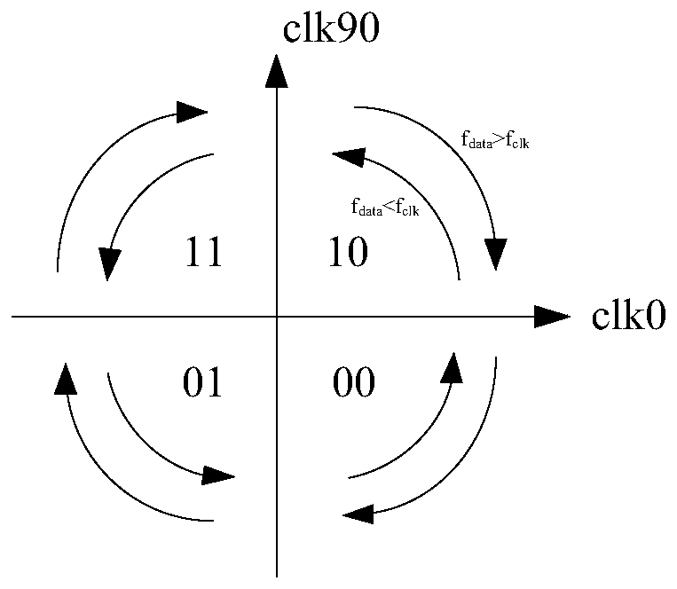
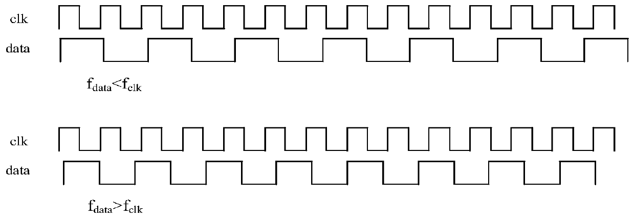
[0005] The technical problem to be solved by the present invention is to overcome the deficiencies of the prior art, provide a frequency and phase detector with a wide pulling range, and solve the problem that the traditional full-rate DFF PD cannot reduce the frequency difference between the data and the clock, resulting in a narrow pulling range. small problem

Method used


Image

  • A phase frequency detector with a wide traction range
  • A phase frequency detector with a wide traction range
  • A phase frequency detector with a wide traction range

Examples


Embodiment Construction

[0022] Embodiments of the present invention will be described below in conjunction with the accompanying drawings.

[0023] like Figure 5 As shown, the present invention has designed a kind of frequency discrimination phase detector of wide pulling range, comprises: first flip-flop D1, second flip-flop D2, the 3rd flip-flop D3, the 4th flip-flop D4, the first latch Q1, second latch Q2, third latch Q3, fourth latch Q4, first XOR gate X1, second XOR gate X2, third XOR gate X4, fourth XOR gate X6 , the first inverter X3, the first NOR gate X5, the second NOR gate X7, the first NOR gate X8, and the second NOR gate X9.

[0024] Wherein, the data input ends of the first to the fourth flip-flops are respectively connected with the clocks clk0, clk45, clk90, clk135, that is, the data input ends of the first flip-flop D1 are connected with the clock clk0, and the data input ends of the second flip-flop D2 are connected with the clock clk0. The clock clk45 is connected, the data inpu...


PUM


Abstract

The invention discloses a phase frequency detector with a wide traction range. The trigger circuit comprises first to fourth triggers, first to fourth latches, a first exclusive-OR gate (X1), a secondexclusive-OR gate (X2), a third exclusive-OR gate (X4), a fourth exclusive-OR gate (X6), a first inverter (X3), a first XNOR gate (X5), a second XNOR gate (X7), a first NOR gate (X8), and a second NOR gate (X9), in which data input terminals of the first to fourth flip-flops are connected to clk0, clk45, clk90, and clk135 respectively, and clock input terminals of the first to fourth flip-flops are connected to input data; the output end of the first NOR gate (X8) is connected to the node Fdn, and the output end of the second NOR gate (X9) is connected to the node Fup. According to the method, PD cycle slip is reduced, the traction range of the PD is expanded, an independent FD loop is eliminated, the traction range, clock jitter and data jitter performance of a CDR system are optimized,and noise and system instability caused by back-and-forth switching of circuit control power between a phase frequency loop and a phase discrimination loop in the CDR are avoided.

Description

technical field [0001] The invention relates to a frequency and phase detector with wide traction range, which belongs to the technical field of analog circuits. Background technique [0002] Clock data restorers are widely used in various high-speed serial communication systems, including optical fiber communication, high-speed serial interface communication and interconnection communication between high-performance chips, etc., and are mainly responsible for generating Clock and retimed recovery of data. Frequency detector FD (Frequency Detector) and phase detector PD (PhaseDetector) are important modules in CDR. FD is responsible for generating the clock signal corresponding to the serial data, and PD is responsible for phase alignment of the clock signal and serial data, so that the clock can retime and recover the data at the best sampling point. [0003] The pulling range, clock jitter, and data jitter of a CDR module directly reflect the performance of the module. ...

Claims


Application Information

Patent Timeline
Patent Type & Authority Applications(China)
IPC IPC(8): H03L7/087H03L7/091
Inventor 吴建辉李长波李红
Owner SOUTHEAST UNIV
Learn More