
Rotary shearing mechanism and hanging net slurry filling machine device

A technology of rotating shearing and rotating shafts, which is applied in the direction of shearing devices, attachments of shearing machines, shearing machine equipment, etc., and can solve the problems of increasing the size of the actuator and occupying a large space

Active Publication Date: 2021-09-24
GUANGDONG BOZHILIN ROBOT CO LTD
View PDF7 Cites 0 Cited by
  • Summary
  • Abstract
  • Description
  • Claims
  • Application Information

AI Technical Summary

Problems solved by technology

[0002] At present, the cutting of the flexible base material of the hanging net grouting machine adopts a scissors-type structure, and the two shearing knives are cut from both sides to the middle, which takes up a lot of space and increases the size of the entire actuator

Method used


Image

  • Rotary shearing mechanism and hanging net slurry filling machine device
  • Rotary shearing mechanism and hanging net slurry filling machine device
  • Rotary shearing mechanism and hanging net slurry filling machine device

Examples


Embodiment

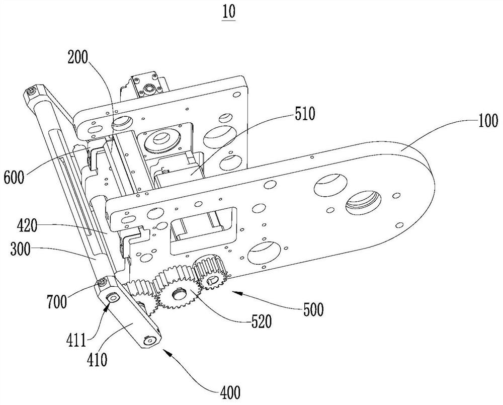
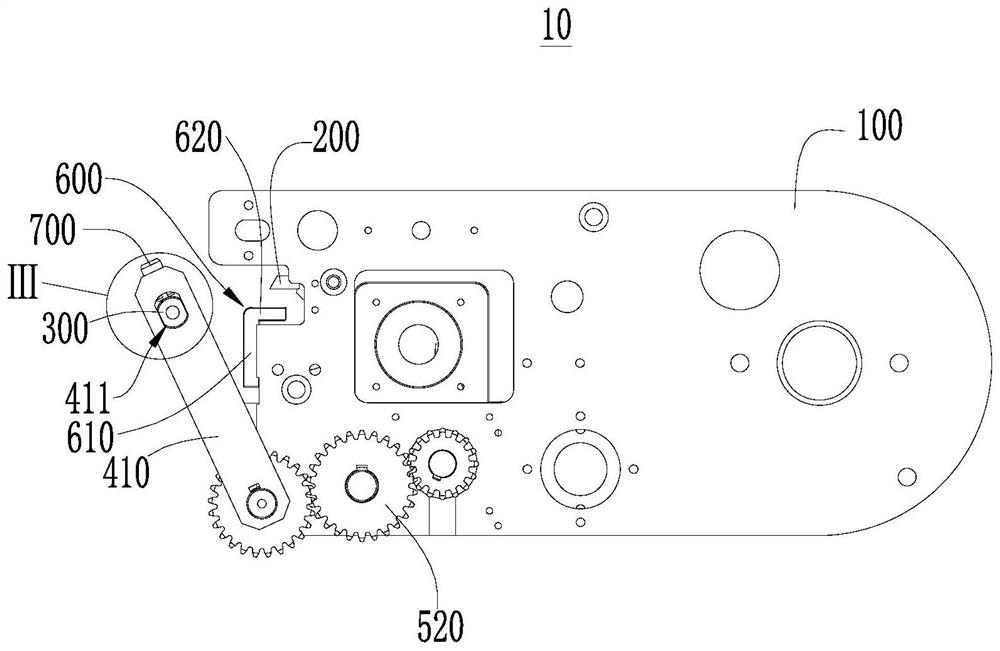
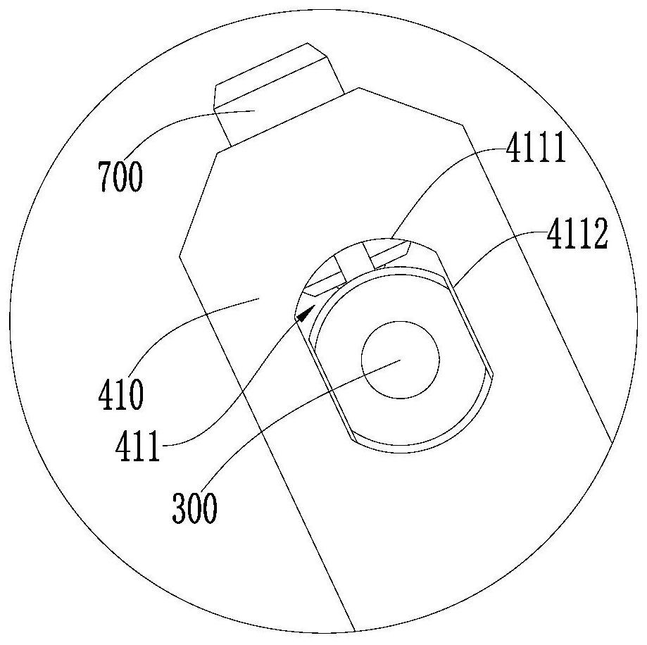
[0029] Please refer to figure 1 This embodiment provides a rotary shear mechanism 10 including a frame 100, a swing rack 400, a first blade 200, a second case 300, and a drive mechanism 500. The oscillating frame 400 is rotatably coupled to the frame 100. The first blade 200 is mounted on the frame 100, and the second case 300 is mounted to the swing rack 400. The drive mechanism 500 is configured to drive the swing frame 400 relative to the frame 100 to cause the first blade 200 to cooperate with the second blade 300 to generate shear operation. By setting the first blade 200 and the frame 100, the first blade 200 is fixed to the rack 100. Set the second blade 300, the swing rack 400, and the drive mechanism 500, connect the second case 300 on the swing frame 400 and drive the swing frame 400 by the drive mechanism 500 to make the second case 300 cooperate with the first blade 200. Generate a shear action. The first blade 200 is fixed, and the second case 300 is swing in one side...


PUM


Abstract

The invention provides a rotary shearing mechanism and a hanging net slurry filling machine device, and relates to the technical field of buildings. The rotary shearing mechanism comprises a rack, a swing frame, a first blade, a second blade and a driving mechanism. The swing frame is rotatably connected to the rack. The first blade is installed on the rack, and the second blade is installed on the swing frame. The driving mechanism is used for driving the swing frame to swing relative to the rack, so that the first blade and the second blade are matched to generate a shearing action. The hanging net slurry filling machine device comprises the rotary shearing mechanism. The first blade of the rotary shearing mechanism is fixed, the swing frame drives the second blade to swing on one side and to be matched with the first blade for shearing, and the occupied space is small. The hanging net slurry filling machine device is small in size and convenient to use.

Description

Technical field [0001] The present application relates to the field of building technology, and in particular, a rotating shear mechanism and a hanging metering machine device are involved. Background technique [0002] At present, the flexible substrate of the hanging mesh filling machine is cut off with scissors, and the two shear knives are clipped from both sides, respectively, and the space is large, and the size of the entire actuator is increased. Inventive content [0003] The purpose of the present application embodiment is to provide a rotary shear mechanism, which is intended to improve the problem of large volume of shear mechanism in the related art. [0004] The present application embodiment provides a rotating shear mechanism including a rack, a swing rack, a first blade, a second blade, and a drive mechanism. The swing holder is rotatably connected to the rack. The first blade is mounted on the rack, and the second blade is mounted in the wiper. The drive mechan...

Claims


Application Information

Patent Timeline
IPC IPC(8): B23D15/04B23D33/00
CPCB23D15/04B23D33/00Y02W30/64
Inventor 易国春黄金烁喻永波张梦杰李海
Owner GUANGDONG BOZHILIN ROBOT CO LTD
Learn More