
Non-contact miniature photoacoustic imaging head and imaging device thereof

A photoacoustic imaging, non-contact technology, applied in measurement devices, material analysis through optical means, instruments, etc., can solve problems such as increasing the difficulty of optical system construction, patient discomfort, and complex system construction, and avoid freedom. Space optical confocal alignment, improve the effect of difficult construction and easy system construction

Active Publication Date: 2021-11-19
SHANGHAI JIAO TONG UNIV
View PDF8 Cites 0 Cited by
  • Summary
  • Abstract
  • Description
  • Claims
  • Application Information

AI Technical Summary

Problems solved by technology

[0003] (1) For the photoacoustic imaging of cerebral blood vessels or capillaries in burnt skin, which have strict hygiene requirements, the contact detection method may cause pollution problems
[0004] (2) When imaging blood vessels in the eye, such as the retina, the use of these ultrasonic coupling agents will cause discomfort to the patient, and even lead to the risk of blindness in severe cases
However, when the sample size is too large and the weight is heavy, for example, when performing photoacoustic remote sensing microscopic imaging on certain parts of humans or other large animals, ordinary electronically controlled displacement platforms cannot meet the requirements
At the same time, when moving a large-volume or heavy-weight sample, it is easy to shake the sample. For a photoacoustic remote sensing microscopic imaging device with a resolution of micron, it will cause the image obtained by scanning to become blurred, or even the scan cannot be completed.
[0009] (2) The photoacoustic remote sensing microscopic imaging device based on free space light is relatively large, which makes it difficult to use in some scenarios, such as photoacoustic scanning inside the oral cavity and inside the digestive tract
[0010] (3) The system construction based on free space light is more complicated
In the photoacoustic remote sensing imaging device based on free space light, multiple optical components need to be used, and it is difficult to ensure the confocality of excitation light and probe light
In addition, when combined with other optical methods, such as fluorescence imaging or optical coherence tomography, the entire imaging device will be particularly complicated, which greatly increases the difficulty of building the optical system, which is not conducive to photoacoustic remote sensing imaging. Further development of micro-imaging technology
[0011] (4) The stability of the optical imaging device based on free space light is not high
However, its imaging head is still based on free-space light, including components such as dichroic mirrors and scanning mirrors, and many of the above-mentioned shortcomings still exist

Method used


Image

  • Non-contact miniature photoacoustic imaging head and imaging device thereof
  • Non-contact miniature photoacoustic imaging head and imaging device thereof
  • Non-contact miniature photoacoustic imaging head and imaging device thereof

Examples


Embodiment Construction

[0037] The following describes the preferred embodiments of the present invention with reference to the accompanying drawings to make the technical content clearer and easier to understand. The present invention can be embodied in many different forms of embodiments, and the protection scope of the present invention is not limited to the embodiments mentioned herein.

[0038] In the drawings, components with the same structure are denoted by the same numerals, and components with similar structures or functions are denoted by similar numerals. The size and thickness of each component shown in the drawings are shown arbitrarily, and the present invention does not limit the size and thickness of each component. In order to make the illustration clearer, the thickness of parts is appropriately exaggerated in some places in the drawings.

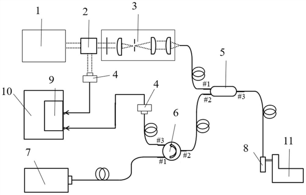
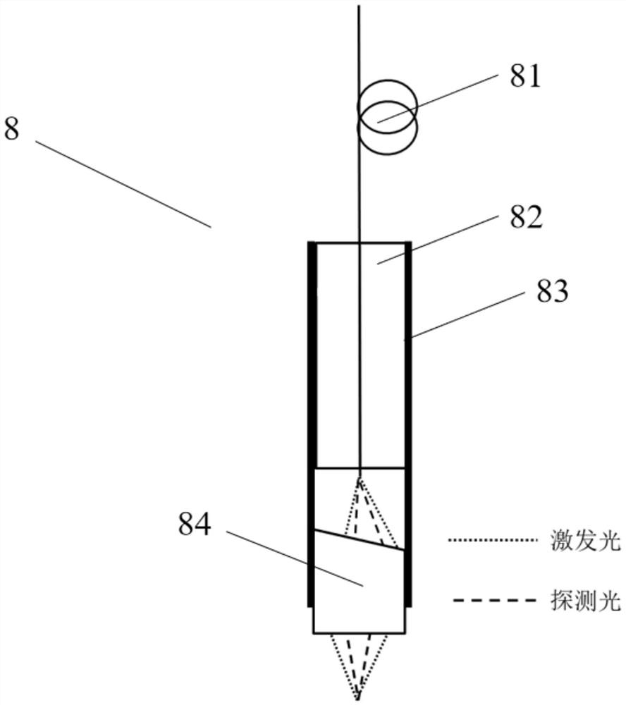
[0039] Such as figure 1 Shown is a non-contact photoacoustic imaging device provided by an embodiment of the present application, including a...


PUM

PropertyMeasurementUnit
diameteraaaaaaaaaa
diameteraaaaaaaaaa

Abstract

The invention provides a non-contact miniature photoacoustic imaging head, which comprises an optical fiber and a lens, and the optical fiber and the lens are coaxially aligned. The invention further provides a non-contact photoacoustic imaging device which comprises the non-contact miniature photoacoustic imaging head, an excitation light source, a detection light source, a beam splitter, a photoelectric detector, a beam expanding and shaping module, a wavelength division multiplexer, an optical fiber circulator and an acquisition card. In non-contact photoacoustic microscopic imaging based on photoacoustic remote sensing, miniaturization of an imaging head, construction simplification and use convenience of an imaging system and simplification of the imaging system in multi-mode imaging development are realized.

Description

technical field [0001] The present application relates to the field of photoacoustic imaging, in particular to a non-contact miniature photoacoustic imaging head and an imaging device thereof. Background technique [0002] Photoacoustic imaging technology has gradually become a powerful tool in the field of biomedicine. In this technique, a pulsed laser with a pulse width of nanoseconds is usually used as excitation light to irradiate the sample. When the photon energy of the laser is absorbed by the sample, the photon energy will be converted into heat, which will generate instantaneous thermal expansion inside the sample. This thermal expansion will cause a pressure change inside the sample, and propagate to the outside of the sample in the form of sound waves, which will be detected by the ultrasonic probe placed around the sample, and the resulting signal is the so-called photoacoustic signal. Since the ultrasonic wave is severely attenuated in the air, if you want to ...

Claims


Application Information

Patent Timeline
Patent Type & Authority Applications(China)
IPC IPC(8): G01N21/17G01N21/01
CPCG01N21/1702G01N21/01
Inventor 陈松良周加胜
Owner SHANGHAI JIAO TONG UNIV
Learn More