Full-automatic loading and unloading positioning device for bowl cutter

A positioning device, fully automatic technology, applied in the direction of positioning device, clamping, support, etc., can solve the problems of inability to clamp and position the gasket block, and there is no mechanized installation method for the gasket block, and achieve the effect of improving production efficiency.

Active Publication Date: 2021-09-24
TAIYUAN UNIV OF TECH
View PDF13 Cites 0 Cited by
  • Summary
  • Abstract
  • Description
  • Claims
  • Application Information

AI Technical Summary

Problems solved by technology

In the process of realizing the present invention, the inventor found that there are at least the following problems in the prior art: due to the particularity of the shape of the bowl knife, the mechanical arm cannot directly clamp and position the gasket block in the small space inside the bowl knife
During the loading and unloading steps of the bowl knife processing, the mechanical arm can complete the positioning and installation of the bowl knife, but there is no mechanized installation method for the installation of the gasket block.

Method used


Image

  • Full-automatic loading and unloading positioning device for bowl cutter
  • Full-automatic loading and unloading positioning device for bowl cutter
  • Full-automatic loading and unloading positioning device for bowl cutter

Examples


Embodiment Construction

[0020] The present invention will be further described below in conjunction with the accompanying drawings.

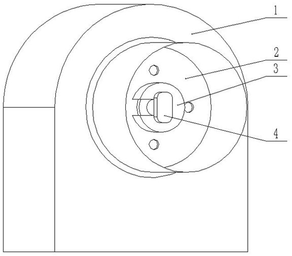
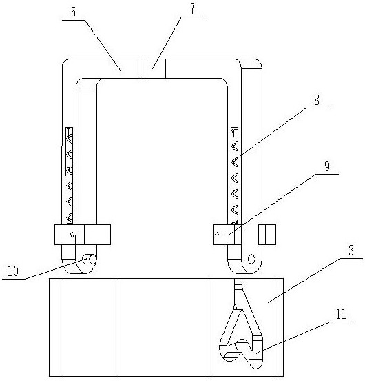
[0021] Such as Figure 2-Figure 4 As shown, a fully automatic loading and unloading positioning device for bowl knives in an embodiment of the present invention includes a clamping frame 5 and a spacer block 3. Support arms are provided on both sides of the clamping frame 5, and the two support arms are connected by a beam. , the support arm is provided with an elastic piece 9, and the support arm is provided with a movable block 9 that is slidably connected along the length direction of the support arm. The member 9 is configured in a compressed state, ie pre-compressed. This creates greater clamping force.

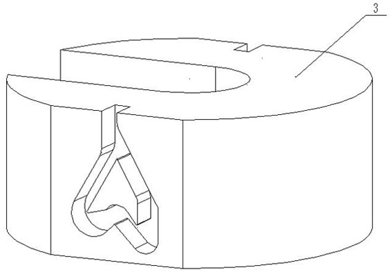
[0022] Both sides of the spacer block 3 are provided with side grooves 11, and a channel for the sliding of the protrusion 10 is provided in the side groove 11. A second angle 15 bent upward is provided in the channel. When the clamping frame 5 moves downward, ...


PUM


Abstract

The invention discloses a full-automatic loading and unloading positioning device for a bowl cutter. The full-automatic bowl cutter loading and unloading positioning device comprises a clamping frame and a gasket block, wherein supporting arms are arranged at the two sides of the clamping frame, the two supporting arms are connected through a cross beam, elastic parts are arranged on the supporting arms, movable blocks which are connected in a sliding manner in the length direction of the supporting arms are arranged on the supporting arms, and the movable blocks are arranged at the bottom ends of the elastic parts; a protruding part is arranged at the inner side of each supporting arm, and the elastic parts are configured to be in a pressed state; side grooves are formed in the two sides of the gasket block, channels used for sliding of the protruding parts are arranged in the side grooves, second bent angles bent upwards are arranged in the channels, and when the clamping frame moves downwards, the protruding parts enter the channels, the movable blocks are pushed by the gasket block, the elastic parts continue to be compressed, and when the clamping frame stops moving, the elastic parts rebounds, the protruding parts slide to the second bent angles, and the clamping frame and the gasket block are fixed; and after the gasket block is fixed to a machine tool, the clamping frame moves downwards again, the protruding parts slide out along the channels, and the clamping frame and the gasket block are separated. The full-automatic loading and unloading positioning device can realize automatic loading and unloading of the bowl cutter gasket block, and improves the production efficiency of the bowl cutter.

Description

technical field [0001] The invention relates to a clamping device, in particular to a fully automatic loading and unloading positioning device for bowl knives. Background technique [0002] In the process of processing the bowl knife of textile machinery accessories, the loading and unloading of the bowl knife on the machine tool mainly depends on manual loading and unloading. Since bowl knives are consumables, the amount of processing required is huge, and manual loading and unloading is difficult to meet the production capacity. Therefore, it is tried to introduce mechanical arms in the production line to replace manpower to realize the loading and unloading of bowl knives. refer to figure 1 , the process of installing the bowl knife 2 on the machine tool: the bowl knife 2 is placed at the concentric position with the rotation center of the machine tool 1, and then the gasket block 3 is added; the gasket block 3 passes through the end of the hydraulic piston rod 4 and is ...

Claims


Application Information

Patent Timeline
Patent Type & Authority Applications(China)
IPC IPC(8): B23Q3/12
CPCB23Q3/12
Inventor 汪成文李标兵
Owner TAIYUAN UNIV OF TECH
Why Eureka
Try Eureka