A flywheel mechanism for belt connection unlocking device

An unlocking device and flywheel technology, which is applied in the docking device of aerospace vehicles, transportation and packaging, and aerospace vehicles, etc., can solve the problems of large impact force loads, etc., to reduce impact, reduce locking force, and extend strap unlocking the effect of time

Active Publication Date: 2022-08-02
SHANGHAI AEROSPACE SYST ENG INST
View PDF5 Cites 0 Cited by
  • Summary
  • Abstract
  • Description
  • Claims
  • Application Information

AI Technical Summary

Problems solved by technology

Since the explosive bolts rely on the explosion or combustion of the gunpowder to drive the functional mechanism to complete the task, the pyrotechnic device has its own insurmountable shortcomings: once used, the impact load on the structure is large when the pyrotechnic product is working, etc.
As a result, a large impact will be generated on the docking surface of the satellite and rocket, which will have an adverse effect on the load of a single aircraft on a satellite or aircraft

Method used


Image

  • A flywheel mechanism for belt connection unlocking device
  • A flywheel mechanism for belt connection unlocking device
  • A flywheel mechanism for belt connection unlocking device

Examples


Embodiment approach 1

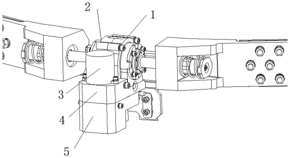
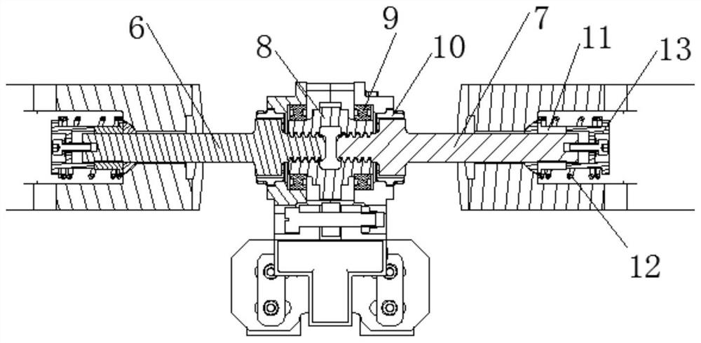
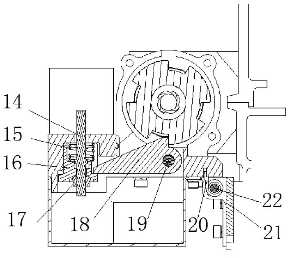
[0029] figure 1 is the structural schematic diagram of the flywheel mechanism used for the strap connection unlocking device according to the embodiment of the present invention, figure 2 It is the structural schematic diagram of the front section of the flywheel mechanism used for the strap connection and unlocking device according to the embodiment of the present invention, image 3 It is a structural schematic diagram of a side view section of a flywheel mechanism used for a strap connection and unlocking device according to an embodiment of the present invention. see Figure 1 to Figure 3 , the flywheel mechanism of the present invention for the strap connection and unlocking device includes a left casing 1, a right casing 2, a separation nut 3, a platform support 4, a collection box 5, a left-handed screw 6, a right-handed screw 7, a flywheel 8, Bearing 9, end cap 10, loading nut 11, compression spring 12, spring end cap 13, double-ended screw 14, unlocking spring 15, ...

Embodiment approach 2

[0037] The difference between this embodiment and Embodiment 1 is that:

[0038] The pin is used to directly realize the constraint of the flywheel 8. When unlocking, the action of pulling the pin can realize the rotation and unlocking of the flywheel 8 without restraint. Except for this, other aspects of this embodiment are the same as those of the first embodiment. It is not repeated here.

[0039] Figure 4 It is a schematic diagram of the installation of the flywheel mechanism for the strap connection and unlocking device according to the embodiment of the present invention. like Figure 4 As shown, the flywheel mechanism of the present invention for the strap connection and unlocking device reduces the large pre-tightening force of the strap to a small locking force, and the flywheel rotates and unlocks to realize the slow release of the strap pre-tightening force.


PUM


Abstract

The present invention proposes a flywheel mechanism for a strap connection and unlocking device, which is characterized by comprising: a left casing, a right casing, a bearing, a flywheel, a left-hand screw, a right-hand screw, a loading nut, a platform support, and a separation nut , Double-ended screw, plunger, bayonet, first shaft, mounting seat, flywheel, left-handed screw, right-handed screw, and loading nut are tape connectors; plunger and bayonet are tape connection unlocking pieces; When inserted into the flywheel slot, the strap connection is realized. When the pin rotates out of the slot, the circumferential constraint of the flywheel is released, the flywheel rotates relative to the left and right screws, and the left and right screws are pulled out from the flywheel to unlock the strap. The invention adopts the flywheel to rotate and unlock instead of the explosive bolt to unlock, which can prolong the unlocking time of the strap and realize the slow release of the pre-tightening force of the strap. The unique unlocking technology can greatly reduce the shock caused by the unlocking of the strap.

Description

technical field [0001] The invention relates to the field of connection and separation of star arrows, implement arrows and the like, in particular to a flywheel mechanism used for a belt connection and unlocking device. Background technique [0002] At present, the strap connection and unlocking device is widely used in the connection and unlocking of the satellite / aircraft and the carrier because of its strong connection rigidity and high reliability. However, the traditional strap connection and unlocking device mainly realizes the radial tightening of the strap by applying pre-tightening force to the explosive bolt. When unlocking, the explosive bolt is detonated, and the strap is released circumferentially to achieve the unlocking function. Because the explosive bolt relies on the explosion or combustion of gunpowder to drive the functional mechanism to complete the task, the pyrotechnic device has its own shortcomings that cannot be overcome: one-time use, the impact l...

Claims


Application Information

Patent Timeline
Patent Type & Authority Patents(China)
IPC IPC(8): B64G1/64
CPCB64G1/645
Inventor 汪全江涛陈鸣亮刘涛任海辽崔国平康士朋沈征辉张哲源
Owner SHANGHAI AEROSPACE SYST ENG INST
Why Eureka
Try Eureka