
A Wellhead Polymer Injection Sampling and Pressure Taking Device

A sampling hole and sampling valve technology, applied in wellbore/well valve device, wellbore/well components, production fluid, etc., can solve the problems of affecting sampling accuracy, complicated operation, large fluid resistance and switching torque, etc. Achieve the effect of being beneficial to production management, accurate sampling data, and small local resistance

Active Publication Date: 2022-03-01
大庆市万物石油机械制造有限公司
View PDF14 Cites 0 Cited by
  • Summary
  • Abstract
  • Description
  • Claims
  • Application Information

AI Technical Summary

Problems solved by technology

When sampling, the above four valves need to be opened in sequence, and after the sampling is completed, they are closed in reverse order, which is cumbersome and time-consuming. As a result, the flow rate of the polymer is fast, and the phenomenon of shear viscosity reduction is serious, which affects the accuracy of sampling; the third is that the four valves on the original sampler all use stop valves, because the structural characteristics of the valves are fluid resistance and switch The torque is large, and the large fluid resistance leads to the problem of rapid flow rate and low polymer viscosity during the opening and closing process, resulting in a large gap between the sampling data and the theoretical value, which cannot truly and accurately reflect the actual injection of the polymer; the switch requires a large torque, and for frequent sampling operations For female workers, it will take time and effort, affecting work efficiency

Method used


Image

  • A Wellhead Polymer Injection Sampling and Pressure Taking Device
  • A Wellhead Polymer Injection Sampling and Pressure Taking Device
  • A Wellhead Polymer Injection Sampling and Pressure Taking Device

Examples


Embodiment Construction

[0029] The following will clearly and completely describe the technical solutions in the embodiments of the present invention with reference to the accompanying drawings in the embodiments of the present invention. Obviously, the described embodiments are only some, not all, embodiments of the present invention. Based on the embodiments of the present invention, all other embodiments obtained by persons of ordinary skill in the art without making creative efforts belong to the protection scope of the present invention.

[0030] The purpose of the present invention is to provide a wellhead polymer injection sampling and pressure taking device to solve the problems existing in the prior art, make the polymer sampling work convenient and fast, reduce the shearing effect of the valve switch on the polymer, and provide accurate sampling data. sex.

[0031] In order to make the above objects, features and advantages of the present invention more comprehensible, the present invention...


PUM


Abstract

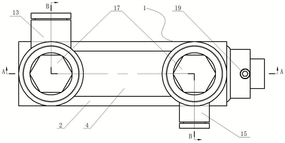
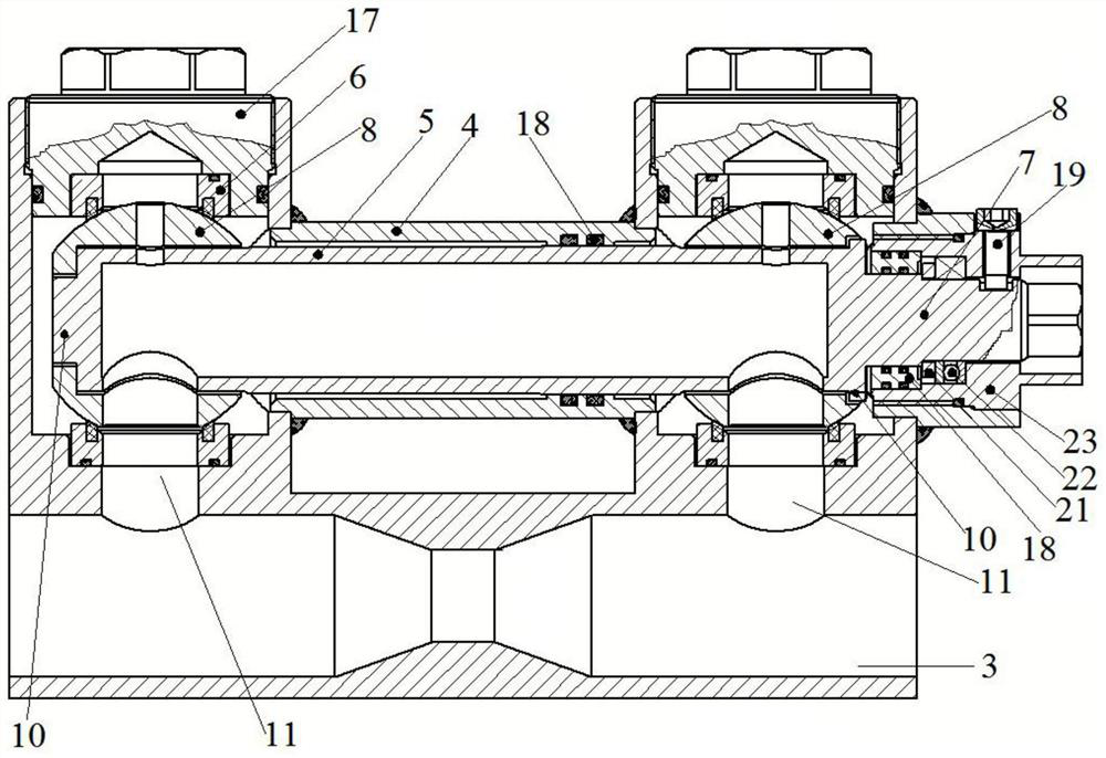
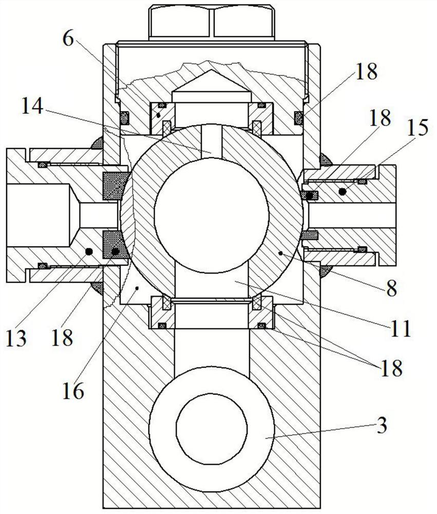
The invention discloses a wellhead polymer injection sampling and pressure taking device, which comprises a circulation main body, a sampling main body and a sampling valve. The circulation main body and the sampling main body are arranged in parallel. The sampling main body is pierced with a sampling valve. Two spheres are arranged on the sampling valve. And the interior of the two spheres is connected through the dial on the valve stem. Each sphere is provided with a sampling hole connected to the dial. The two sampling holes can be connected to the flow holes at both ends of the flow body at the same time. There is a sampling plug, the sampling hole can match the sampling plug, and the flow body is set on the pipeline that needs to be sampled. The invention uses a sampling valve connected inside two spheres to quickly open and close the sampling cylinder at the same time. The sampling time is short and the local resistance is small, which reduces the loss of fluid viscosity caused by the shearing of the valve body and makes the sampling test results more real. It reflects the viscosity of the fluid in the pipeline, the sampling data is accurate, and the structure is simple, the operation is convenient, the performance is reliable, and it is beneficial to production management.

Description

technical field [0001] The invention relates to the technical field of oil drilling equipment and accessories, in particular to a wellhead polymer injection sampling and pressure taking device. Background technique [0002] The wellhead polymer injection sampling and pressure taking device is widely used in the sampling process of oilfield polymer injection wells. It can accurately obtain the physical parameters of the polymer in the front section of the injection wellhead device and provide a reference for production. [0003] However, there are several problems in the wellhead injection sampling and pressure taking device currently in use: firstly, there are many valves arranged on the sampler, including inlet valve, outlet valve, sampling valve and vent valve. When sampling, the above four valves need to be opened in sequence, and after the sampling is completed, they are closed in reverse order, which is cumbersome and time-consuming. As a result, the flow rate of the p...

Claims


Application Information

Patent Timeline
Patent Type & Authority Patents(China)
IPC IPC(8): E21B49/08E21B34/02E21B43/22
CPCE21B49/086E21B34/02E21B43/16
Inventor 徐占有
Owner 大庆市万物石油机械制造有限公司
Learn More