

Semi-floating half-shaft rotation bending fatigue test device and method based on drive axle assembly
A driving axle assembly and bending fatigue technology, which is applied in the field of semi-floating half-shaft rotating bending fatigue test device based on the driving axle assembly, can solve the problem of complex structure, high cost, and inability to verify the life of the half-shaft plate, bolts and bearings and other issues to achieve the effect of ensuring accuracy
Pending Publication Date: 2021-09-24
SICHUAN JIANAN IND
View PDF14 Cites 2 Cited by
- Summary
- Abstract
- Description
- Claims
- Application Information
AI Technical Summary
Problems solved by technology
However, in the current industry standard, there are only half shaft static torsion test and half shaft torsional fatigue test. The two tests can only verify the fatigue life of the half shaft spline and rod, but cannot verify the life of the half shaft disc, bolts and bearings.
[0003] At present, there are equipments on the market for verifying the fatigue life
Method used
View moreImage
Smart ImageViewing Examples

Examples
 PUM
 Abstract
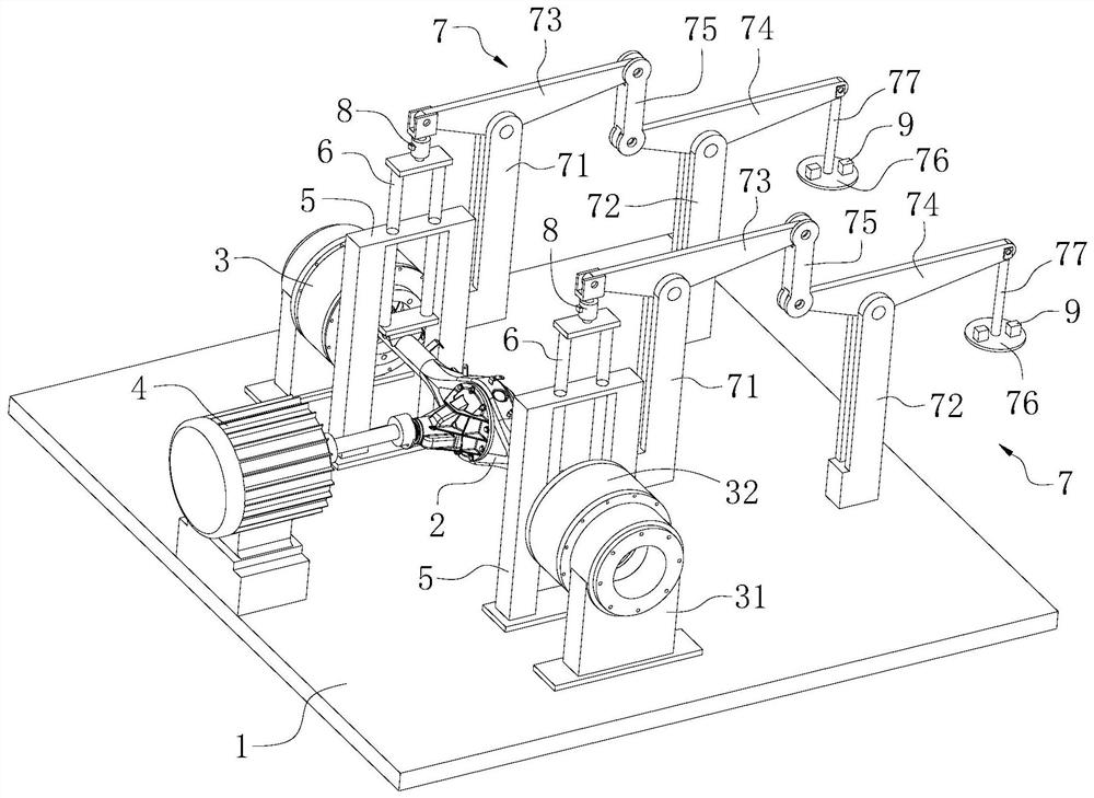
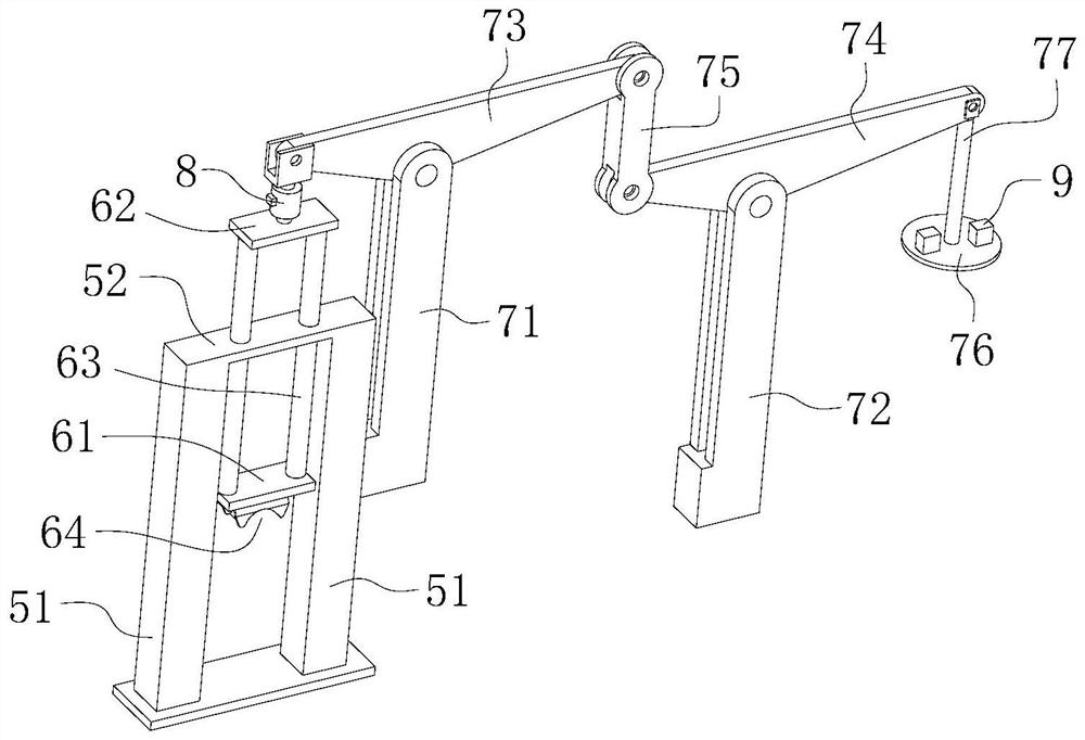
The invention relates to the technical field of drive axle test devices, and provides a semi-floating half-shaft rotation bending fatigue test device based on an drive axle assembly. The device comprises a test platform, two rim fixing devices mounted on the test platform, a drive motor and two loading mechanisms; each loading mechanism comprises a support frame mounted on the test platform and a stress application frame which is vertically mounted on the support frame in a sliding manner, and the lower end of the stress application frame is used for being propped against and matching a test sample bridge; and the device further comprises a lever mechanism which is arranged on the test platform and is used for applying downward acting force to the stress application frames. By arranging the lever mechanism and utilizing the lever principle, the gravity of a small mass block is amplified and is loaded to the test sample bridge through the stress application frames, meanwhile, the gravity of the mass block is not influenced by factors such as test device operation, test sample bridge rigidity change, test device manufacturing and mounting errors and the like, and the vertical load borne by the test sample bridge in the test process is ensured to be constant, so that the accuracy of the test result is improved.
Description
technical field [0001] The invention relates to the technical field of drive axle test devices, in particular to a drive axle assembly-based semi-floating half-axis rotating bending fatigue test device and method. Background technique [0002] When the drive axle equipped with semi-floating half-shaft assembly is running, the half-shaft not only bears the torque, but also bears the radial load exerted on the half-shaft by the self-weight of the whole vehicle and the road surface excitation from the half-shaft bolt to the bearing. However, the current industry standards only have the half shaft static torsion test and the half shaft torsional fatigue test. The two tests can only verify the fatigue life of the half shaft spline and rod, but cannot verify the life of the half shaft disc, bolts and bearings. [0003] At present, there are equipments on the market for verifying the fatigue life of the half shaft plate, bolts and bearings, but the structures of these equipments ar...
Claims
Login to View More Application Information
Patent Timeline
 IPC IPC(8): G01M13/00G01M17/007G01N3/20G01N3/14G01N3/02
CPCG01M13/00G01M17/007G01N3/20G01N3/14G01N3/02G01N2203/0028G01N2203/0033G01N2203/0073
Inventor 李自平郝锌杨钧浩杨雷孙伟元陈正康陈忠敏高为蒋屹尹晶磊李杰张熙胡礼曹敏
Owner SICHUAN JIANAN IND