Bolt-shaped suturing instrument, bolt-shaped suturing mechanism, bolt-shaped suturing device and endoscope suturing method
A stapler and bolt-shaped technology, applied in the field of medical devices, can solve the problems of limited opening angle and closed firmness of endoscopic metal clips, poor flexibility and firmness, difficulty in meeting the needs of surgery, etc., to achieve High stitching precision and reliability, easy to use, and guaranteed effect
- Summary
- Abstract
- Description
- Claims
- Application Information
AI Technical Summary
Problems solved by technology
Method used
Image
Examples
Embodiment 1
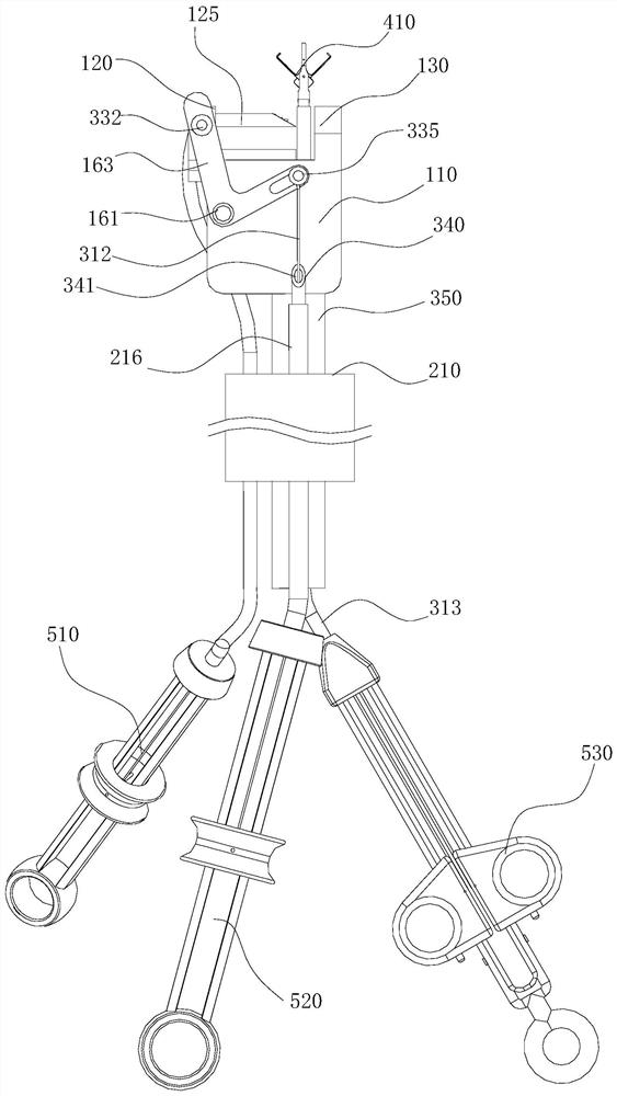
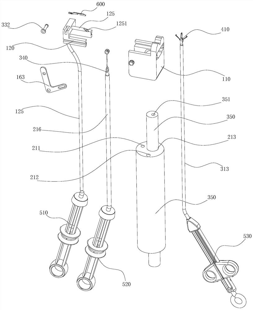
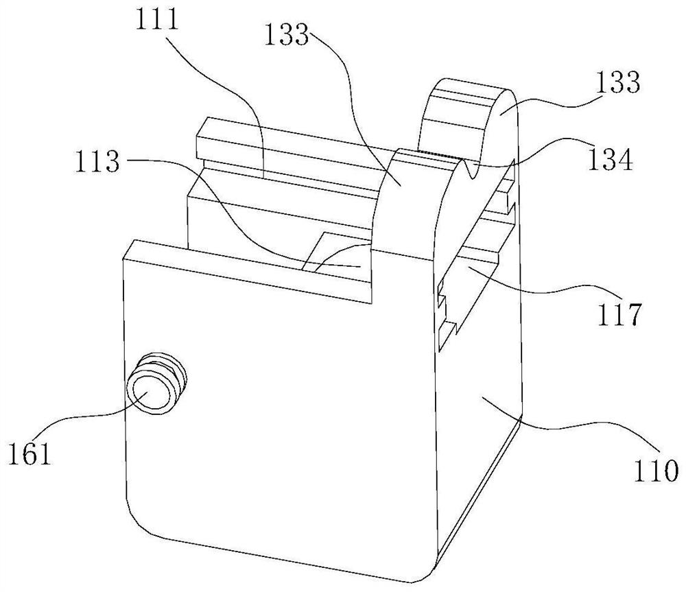
[0081] Such as Figure 1 to Figure 13 As shown, the plug-shaped suturing device, the plug-shaped suturing device described in this embodiment is mainly used for suturing the digestive tract, and it includes: a guide lumen 210, a clamp 410, an endoscope 350, a first operating member 510, a second The operating member 520, the third operating member 530 and the plug-shaped stapler.
[0082] The guide lumen tube 210 has a first guide cavity 211, a second guide cavity 212, and a third guide cavity 213, and a first push-pull member 312 is arranged in the second guide cavity 212. In this embodiment, the first push-pull member 312 adopts It is made of guide steel wire with certain elasticity and rigidity, and its function will be described later. An endoscope 350 is built in the third guide cavity 213, an endoscope cavity 351 is arranged in the endoscope cavity 350, and a control tube is arranged in the endoscope cavity 351. Cable 313. The guide lumen 210 is elastic, bendable and n...
Embodiment 2
[0107] Such as Figure 14 As shown, the difference between this embodiment and Embodiment 1 is that in this embodiment, a closed guide groove 1231 is provided on the first collision member 120, and the closed guide groove 1231 is connected with the second The pin shaft 332 is in sliding fit. The principle is the same as that of the first embodiment, and will not be repeated here.
Embodiment 3
[0109] Such as Figure 15 , Figure 16 As shown, in this embodiment, both ends of the first transmission member 163 are bar hole structures, that is, the force application part 166 and the force transmission part 167 of the first transmission member 163 are respectively the first chute, and the second Two chute, the front end of the first push-pull member 312 is provided with a fifth pin shaft 335, the fifth pin shaft 335 is slidingly matched with the first chute, and a second pin shaft 332 is provided on the first collision member 120 , the second pin shaft 332 cooperates with the second sliding groove.
PUM
 Abstract
Description
Claims
Application Information
 - R&D
- Intellectual Property
- Life Sciences
- Materials
- Tech Scout
- Unparalleled Data Quality
- Higher Quality Content
- 60% Fewer Hallucinations
Browse by: Latest US Patents, China's latest patents, Technical Efficacy Thesaurus, Application Domain, Technology Topic, Popular Technical Reports.
© 2025 PatSnap. All rights reserved.Legal|Privacy policy|Modern Slavery Act Transparency Statement|Sitemap|About US| Contact US: help@patsnap.com


