Anti-deformation punching device for stainless steel pipe
A stainless steel tube and anti-deformation technology, which is applied in the field of punching and cutting devices, can solve the problems of reduced work efficiency, low qualified rate of finished products, and cumbersome problems, and achieve the effects of reducing labor intensity, improving work safety, and improving work efficiency
- Summary
- Abstract
- Description
- Claims
- Application Information
AI Technical Summary
Problems solved by technology
Method used
Image

Examples
Embodiment 1
[0033] like Figure 7As shown, in this embodiment, in order to facilitate the placement of the steel pipe body 8 in the discharge mechanism 5, the limit plates 35 are respectively fixedly installed on the side walls of the two sides of the second material guide plate 28, and the limit plates 35 are located in the movable position. Between the blocks 29, the first sliding block 36 is fixedly installed on the side walls of both sides of the limiting plate 35, the first sliding block 36 passes through the bar-shaped through groove 31, and the first sliding block 36 is movably installed in the second sliding groove 32, the side wall of the limit plate 35 is provided with a through spring groove 37, and a retaining ring 39 is fixedly installed in the two ends of the spring groove 37, and a second compression spring 38 is fixedly installed in the groove of the spring groove 37. The two ends of the two compression springs 38 are fixedly installed with a limit clamp 40, and the limit ...
Embodiment 2
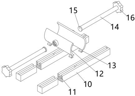
[0035] like Image 6 As shown, in this embodiment, in order to realize the automatic discharging operation of the steel pipe body 8, the discharging frame 24 is fixedly installed on the first material guide plate 20, and the discharging frame 24 is located between the support rods 23, and the discharging frame Both sides of the inner wall of 24 are provided with a group of symmetrical grooves 25 respectively, and fixed rod 26 is fixedly installed in the groove of groove 25, and first compression spring 27 is set on the body of fixed rod 26, and the top surface of first compression spring 27 Fixedly installed on the top surface in the groove of the groove 25, the outer wall both sides of the discharge frame 24 are respectively provided with a strip-shaped through-slot 31, and the strip-shaped through-slot 31 is located between the grooves 25, and the strip-shaped through-slot 31 Both sides of the groove wall are respectively provided with a second sliding groove 32, and a group...
Embodiment 3
[0037] like Figure 8 As shown, in this embodiment, in order to push the steel pipe body 8 onto the clamping mechanism 3 in a fully automatic manner, the rear end of the punching machine body 1 is fixedly equipped with a support cross bar 42, and the top surface of the support cross bar 42 A symmetrical support vertical bar 43 is fixedly installed, and two groups of symmetrical mounting blocks 44 present a semi-circular shape. There is a side block 45, the top surface of the side block 45 is provided with a through hole 46, the bolt 47 passes through the upper and lower symmetrical side block 45 and extends to the outside, the nut 48 is threaded with the bolt 47, and the electric push rod 49 is located on the mounting block 44, and the front end of the electric push rod 49 is fixedly equipped with a push piece 50, the bottom surface of the push piece 50 is fixedly installed with a second sliding block 51, and the second sliding block 51 is movably installed in the first slidin...
PUM
 Abstract
Description
Claims
Application Information
 - R&D Engineer
- R&D Manager
- IP Professional
- Industry Leading Data Capabilities
- Powerful AI technology
- Patent DNA Extraction
Browse by: Latest US Patents, China's latest patents, Technical Efficacy Thesaurus, Application Domain, Technology Topic.
© 2024 PatSnap. All rights reserved.Legal|Privacy policy|Modern Slavery Act Transparency Statement|Sitemap