Manufacturing and machining machine and machining method for reducing copper pipe connector

A technology for processing machinery and connectors, which is applied in the field of grinding and manufacturing of copper pipe connectors, and can solve the problems of rough inner wall, discharge of waste chips, and burrs on the surface of copper tube connectors with different diameters.

Active Publication Date: 2021-09-28
江苏隆凯森机械科技有限公司
View PDF7 Cites 0 Cited by
  • Summary
  • Abstract
  • Description
  • Claims
  • Application Information

AI Technical Summary

Problems solved by technology

[0002] The copper pipe joints that increase or decrease the diameter of the pipeline are called different-diameter copper pipe joints. The different-diameter copper pipe joints are used at the diameter of the pipe. Reduced diameter and expanded diameter pressing, for certain specifications of different diameter copper pipe connectors can also be used stamping forming method, when using stamping forming method to make different diameter copper pipe connectors, the surface of different diameter copper pipe connectors is prone to burrs and other defects , affecting subsequent use
[0003] The existing manufacturing and processing machinery often has the following problems when manufacturing and processing the joints of copper pipes with different diameters: (1)

Method used


Image

  • Manufacturing and machining machine and machining method for reducing copper pipe connector
  • Manufacturing and machining machine and machining method for reducing copper pipe connector
  • Manufacturing and machining machine and machining method for reducing copper pipe connector

Examples


Example Embodiment

[0036] In order to make the technical means, the creation of the present invention, the purpose and energy is easy to understand, the following combinations Figure 1 to 11 Further, the invention is further illustrated.

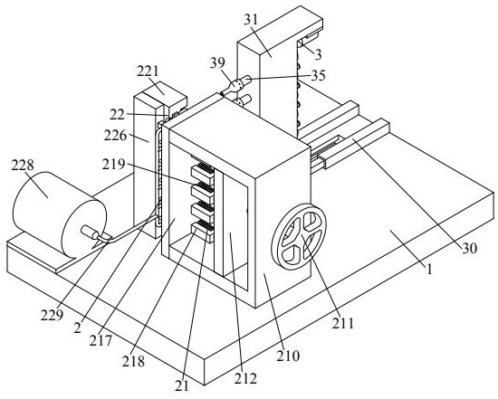
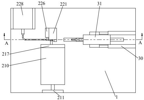
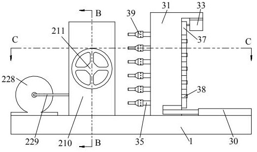
[0037] An aerated copper pipe connection head manufacturing machine, including the bottom plate 1, the fixing device 2, and the grinding device 3, and the upper end is mounted in the upper end of the bottom plate 1, and the fixing device 2 is disposed on the right side of the fixing device 3, the grinding device 3. Installed on the top of the upper end of the bottom plate 1.

[0038] like figure 1 As shown, the fixing device 2 includes a fixing mechanism 21 and a tensioning mechanism 22, and the upper end of the bottom plate 1 is sequentially mounted from the back to the back to the locking mechanism 22, and when the specific operation, the absence of the absence of treatment The copper pipe connection head is placed between the fixing mechanism 21 and the tension...


PUM


Abstract

The invention relates to the technical field of copper pipe connector manufacturing, in particular to a manufacturing and machining machine and machining method for a reducing copper pipe connector. The inner wall of the reducing copper pipe connector is ground through cooperation of an arranged bottom plate, an arranged fixing device and an arranged grinding device; and according to the manufacturing and machining machine and machining method for the reducing copper pipe connector, the problems that when an existing connector manufacturing and machining machine is used for machining the reducing copper pipe connector, generally, only the outer surface of the reducing copper pipe connector is ground, but the inner wall of the reducing copper pipe connector is not ground, accordingly, the surface of the inner wall is rough, and the existing connector manufacturing and machining machine usually begins to grind the reducing copper pipe connector after clamping and fixing the reducing copper pipe connector, scraps generated by grinding cannot be discharged in time in the grinding process, accordingly, the scraps are adhered to a grinding mechanism, and then the situation that the reducing copper pipe connector is scratched by the scraps during grinding are avoided.

Description

technical field [0001] The invention relates to the technical field of polishing and manufacturing copper pipe connectors, in particular to a manufacturing and processing machine and processing method for copper pipe connectors with different diameters. Background technique [0002] The copper pipe joints that increase or decrease the diameter of the pipeline are called different-diameter copper pipe joints. The different-diameter copper pipe joints are used at the diameter of the pipe. Reduced diameter and expanded diameter pressing, for certain specifications of different diameter copper pipe connectors can also be used stamping forming method, when using stamping forming method to make different diameter copper pipe connectors, the surface of different diameter copper pipe connectors is prone to burrs and other defects , affecting subsequent use. [0003] The existing manufacturing and processing machinery often has the following problems when manufacturing and processin...

Claims


Application Information

Patent Timeline
IPC IPC(8): B24B9/04B24B55/06B24B41/06B24B47/12B24B41/02
CPCB24B9/04B24B55/06B24B41/06B24B47/12B24B41/02
Inventor 李鑫
Owner 江苏隆凯森机械科技有限公司
Why Eureka
Try Eureka