Reversing switch

A reverse switch and switch technology, applied in the direction of electrical components, etc., can solve the problems of insufficient positioning and guiding structures, wiring screws without positioning structures, static contacts and moving contacts without positioning structures, etc.

Pending Publication Date: 2019-07-19
ZHEJIANG CHINT ELECTRIC CO LTD
View PDF6 Cites 0 Cited by
  • Summary
  • Abstract
  • Description
  • Claims
  • Application Information

AI Technical Summary

Problems solved by technology

[0003] 1. The wiring terminals are basically a structure of a pressure plate or a wiring frame plus a wiring screw, or a standard screw with a flat pad is used directly, and there is no positioning structure on both sides of the wiring screw, so the mechanical properties of the wiring terminal are difficult to meet the requirements. In addition It is also difficult to guarantee the key parameters such as the electrical clearance of the product;
[0004] 2. There is no positioning structure for the static contact and the moving contact, and it is easy to cause product stuck or poor contact due to improper assembly;
[0005] 3. There is not enough positioning and guiding structure between the upper base assembly and the lower base assembly, and between the lower base assembly and the bracket, resulting in inconvenient assembly and unreliable positioning, so that the upper base assembly and the lower base assembly are assembled Offset occurs during use and affects the reliable action of the reversing switch;
[0006] 4. The lower base assembly does not have a fool-proof structure, which may easily lead to installation errors of the upper base assembly and the lower base assembly, which is not conducive to improving the assembly efficiency of the reversing switch

Method used


Image

  • Reversing switch
  • Reversing switch
  • Reversing switch

Examples


Embodiment Construction

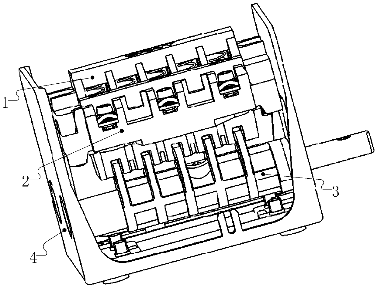
[0050] The following is attached Figure 1-20 The given examples further illustrate the specific implementation of the reversing switch of the present invention. The reversing switch of the present invention is not limited to the description of the following embodiments.

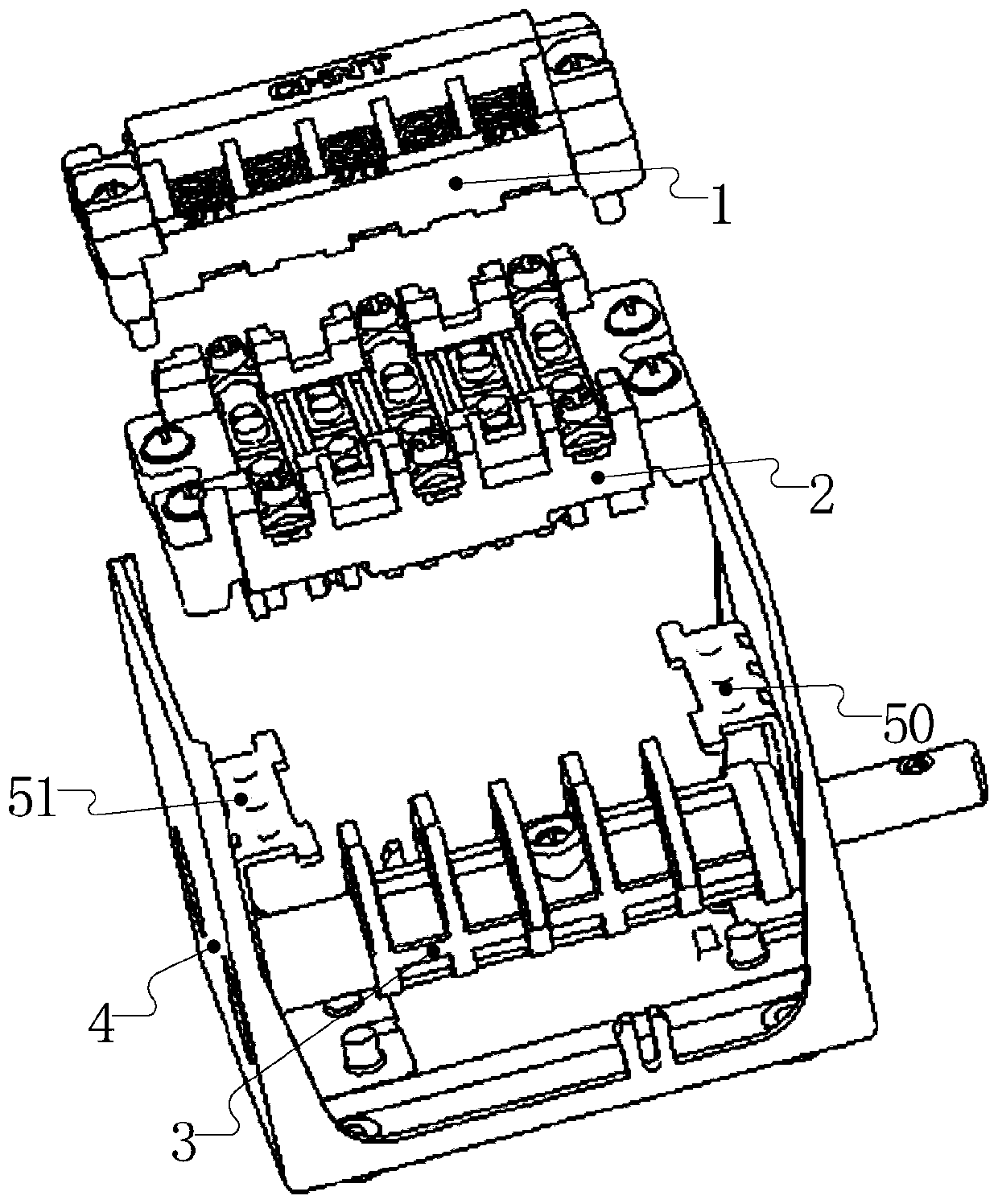
[0051] The reversing switch of the present invention includes a switch housing 4 and an upper base assembly 1, a lower base assembly 2, a transmission mechanism 3, and a bracket 5 arranged in the switch housing 4; one end of the bracket 5 is connected to the housing 4 connected, the other end is connected to the upper base assembly 1 and the lower base assembly 2 respectively, the transmission mechanism 3 is connected to the bracket 5 in rotation, and the upper base assembly 1 and the transmission mechanism 3 are respectively located on both sides of the lower base assembly 2;

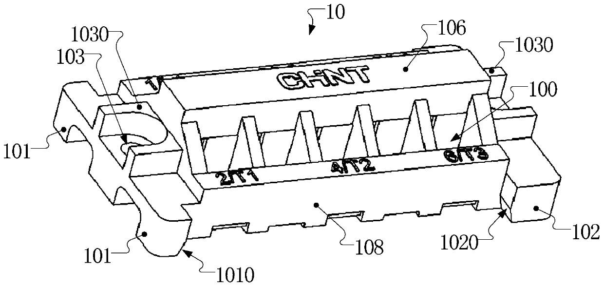
[0052] The lower base assembly 2 includes a lower base 20, and the lower base 20 includes a first assembly side A that cooperates ...


PUM


Abstract

The invention relates to the field of low-voltage electrical appliance, in particular to a reversing switch. The reversing switch comprises a switch shell and an upper substrate assembly, a lower substrate assembly, a transmission mechanism and a support which are arranged in the switch shell, wherein one end of the support is connected with the switch shell, the other end of the switch shell is rotatably connected with the upper substrate assembly, the lower substrate assembly, the transmission mechanism and the support, the upper substrate assembly and the transmission mechanism are respectively arranged at two sides of the lower substrate assembly, a lower substrate also comprises a lower substrate left positioning table and a lower substrate right positioning table, the width of the lower substrate left positioning table is smaller than the width of the lower substrate right positioning table, the width of a left end of a boss is larger than the width of a right end of the boss, aleft support limitation groove is matched with the left end of the boss, and a right support limitation groove is matched with the right end of the boss. The reversing switch is simple and rapid to assemble.

Description

technical field [0001] The invention relates to the field of low-voltage electrical appliances, in particular to a reversing switch. Background technique [0002] Most of the existing reversing switches have the following problems: [0003] 1. The wiring terminals are basically a structure of a pressure plate or a wiring frame plus a wiring screw, or a standard screw with a flat pad is used directly, and there is no positioning structure on both sides of the wiring screw, so the mechanical properties of the wiring terminal are difficult to meet the requirements. In addition It is also difficult to guarantee the key parameters such as the electrical clearance of the product; [0004] 2. There is no positioning structure for the static contact and the moving contact, and it is easy to cause product stuck or poor contact due to improper assembly; [0005] 3. There is not enough positioning and guiding structure between the upper base assembly and the lower base assembly, and ...

Claims


Application Information

Patent Timeline
Patent Type & Authority Applications(China)
IPC IPC(8): H01H21/12
CPCH01H21/12
Inventor 叶圣兵郑乾俊肖体锋朱映平陈律帆
Owner ZHEJIANG CHINT ELECTRIC CO LTD
Why Eureka
Try Eureka