
Connecting joint of fabricated steel-timber combined truss

A technology of combining trusses and connecting nodes, which is applied in the direction of architecture and building construction, can solve problems such as failure to meet structural force requirements, low installation efficiency, and large node loads, and achieve good architectural applicability, improve installation efficiency, and improve The effect of applicability

Inactive Publication Date: 2021-09-28
厦门中建东北设计院有限公司
View PDF8 Cites 1 Cited by
  • Summary
  • Abstract
  • Description
  • Claims
  • Application Information

AI Technical Summary

Problems solved by technology

[0002] At present, as the key part of the truss, the connection node is often damaged before the component, so the material properties of the component cannot be fully utilized, and the design principle of "strong node, weak component" is not satisfied
[0003] In traditional wood structures, tooth-plate connections or tooth connections are commonly used. Existing studies have shown that this type of connection has no obvious plastic deformation when it is damaged, and it belongs to brittle failure.
In the steel-wood composite truss, due to the large span of the truss, the internal force of the member is significantly higher than that of the traditional wood truss structure, and the loads on the nodes are relatively large. The traditional nodes can no longer meet the structural force requirements.
At the same time, the steel-wood composite truss has just started in China, and the existing few joint forms are mostly complex in structure and low in installation efficiency, so it needs to be improved

Method used


Image

  • Connecting joint of fabricated steel-timber combined truss
  • Connecting joint of fabricated steel-timber combined truss
  • Connecting joint of fabricated steel-timber combined truss

Examples


Embodiment 1

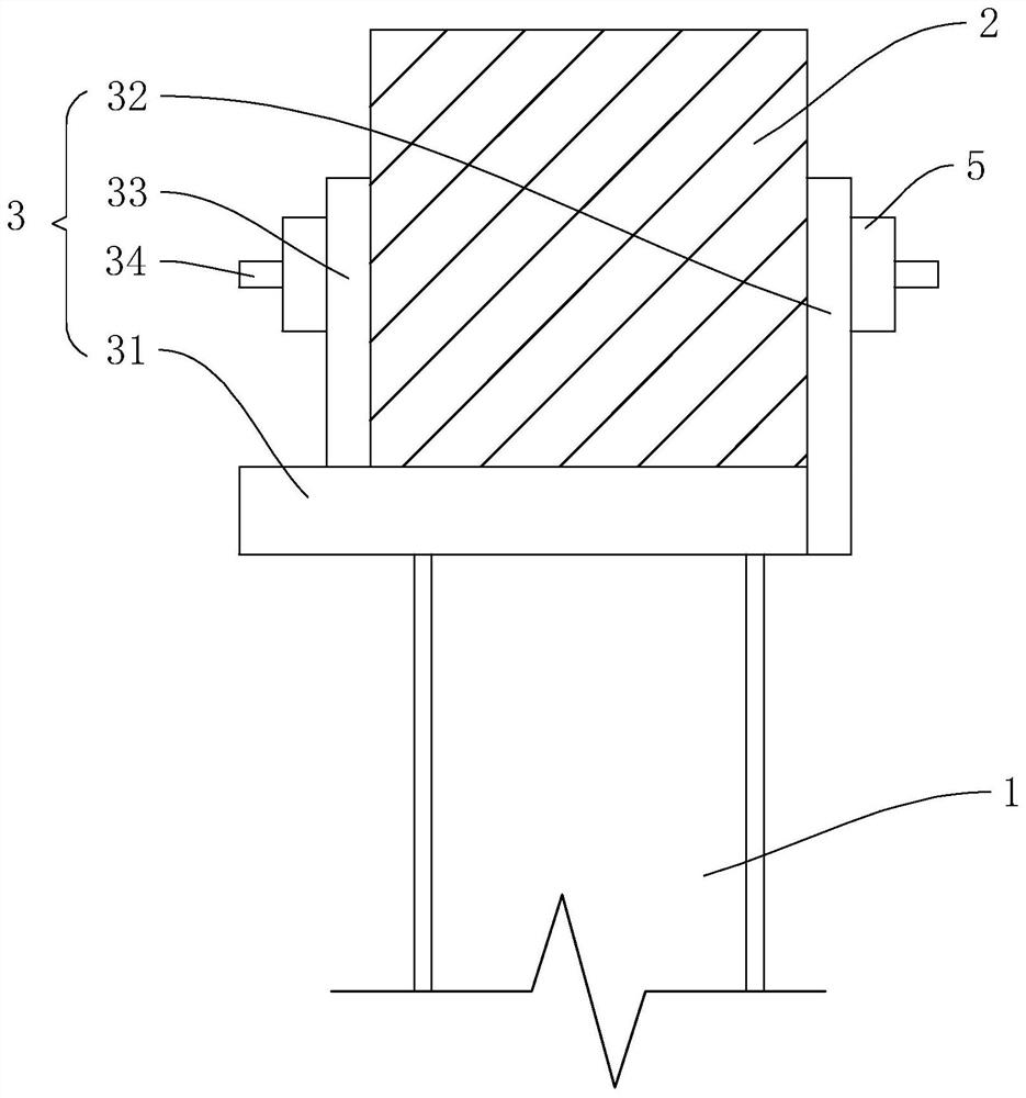
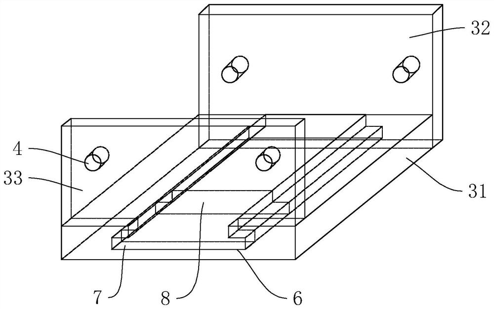
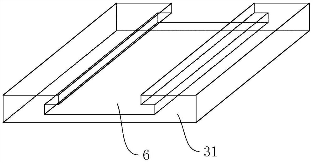
[0042] refer to figure 1 , figure 2 As shown, the connection node includes a steel member 1, a square log 2 and a connection assembly 3, the steel member 1 and the square log 2 are connected through a connection assembly 3, and the connection assembly 3 includes a connection plate 31, a first limit plate 32, a second limit plate Plate 33 and locking member 34, the first limiting plate 32 and the second limiting plate 33 are clamped to the square log 2 both sides, the first limiting plate 32, the second limiting plate 33 and the square log 2 are all provided with The mounting holes 4 provided on the same axis, the locking member 34 passes through each mounting hole 4 and cooperates with the nut 5 to lock and fix the first limiting plate 32 and the second limiting plate 33 to both sides of the square wood 2, the first limiting plate Both the lower end of the plate 32 and the second limiting plate 33 are connected with the connecting plate 31, and the lower end of the connectin...

Embodiment 2

[0048] refer to Figure 5 As shown, the difference between this embodiment and Embodiment 1 is that the filling plate 8 is divided into several sub-boards of equal specifications and spliced ​​together, and the arrangement direction of each sub-board is consistent with the sliding direction of the second limiting plate 33 .

[0049] The implementation principle of embodiment 2 is as follows: the difference from embodiment 1 is that when plugging in the filler boards 8, a corresponding number of sub-boards are plugged and installed according to the actual site conditions.

Embodiment 3

[0051] refer to Figure 6 , Figure 7 As shown, the difference between this embodiment and Embodiment 1 is that the lower end of the connecting plate 31 is welded and fixed with the first ear plate 9, the end of the steel member 1 is fixed with the end plate 11, and the end plate 11 is fixed with the second ear plate 10. In this embodiment, there are two pieces of the first lug plate 9, and one piece of the second lug plate 10. The second lug plate 10 and the two pieces of the first lug plate 9 are coaxially penetrated with a shaft hole 12, corresponding to the shaft A pin shaft 13 is rotatably installed in the hole 12 , thereby realizing the hinge connection effect between the first ear plate 9 and the second ear plate 10 , and further realizing the oblique connection between the steel member 1 and the square timber 2 .

[0052] The implementation principle of Embodiment 3 is as follows: the difference from Embodiment 1 is that before the on-site construction, the first ear ...


PUM


Abstract

The invention relates to a connecting joint of a fabricated steel-timber combined truss, and relates to the technical field of building structures. The connecting joint mainly comprises a steel member, square timber and a connecting assembly, the steel member is connected with the square timber through the connecting assembly, and the connecting assembly comprises a connecting plate, a first limiting plate, a second limiting plate and locking pieces; and the first limiting plate and the second limiting plate are clamped to the two sides of the square timber, the first limiting plate, the second limiting plate and the square timber are provided with mounting holes which are formed in the same axis, and the locking pieces penetrate through the mounting holes and then are matched with nuts to lock and fix the first limiting plate and the second limiting plate to the two sides of the square timber. The lower ends of the first limiting plate and the second limiting plate are connected with a connecting plate, and the lower end face of the connecting plate is welded and fixed to the steel member. The connecting joint has the effect of improving the mounting efficiency of the steel-timber combined truss.

Description

technical field [0001] The present application relates to the technical field of building structures, in particular to a connection node of an assembled steel-wood composite truss. Background technique [0002] At present, as the key part of the truss, the connection nodes are often damaged before the components, so the material properties of the components cannot be fully utilized, and the design principle of "strong nodes, weak components" is not satisfied. [0003] In traditional wood structures, tooth-plate connections or tooth connections are commonly used. Existing studies have shown that this type of connection does not have obvious plastic deformation when it is damaged, and it belongs to brittle failure. In the steel-wood composite truss, due to the large span of the truss, the internal force of the member is significantly higher than that of the traditional wood truss structure, and the loads on the nodes are relatively large. The traditional nodes can no longer me...

Claims


Application Information

Patent Timeline
Patent Type & Authority Applications(China)
IPC IPC(8): E04B1/19
CPCE04B1/19E04B1/1903E04B2001/1975
Inventor 林麟珲王雅文罗军
Owner 厦门中建东北设计院有限公司
Learn More