Universal joint pin type gimbal seat with three bearings for bearing force

A cross shaft and three-bearing technology, which is applied in the field of gimbals, can solve problems such as work interference of gimbals, increase design cycle and cost, and affect assembly stability and bearing coordination stability, etc., to achieve direct thrust transmission, good axial rigidity, Effect on reducing seizure and gluing problems

Pending Publication Date: 2021-09-28
北京星河动力航天科技股份有限公司 +2
View PDF0 Cites 0 Cited by
  • Summary
  • Abstract
  • Description
  • Claims
  • Application Information

AI Technical Summary

Problems solved by technology

However, in the actual design process, due to the nonlinear influence of the lubricating coating, the bearing clearance is often verified and improved through static tests and swing tests, which will increase the design cycle and cost
In addition, the gimbal is usually limited by the swing angle. Generally, the gimbal is limited by the motion interference between the supports. Under the action of a huge thrust, the impact of the support will affect the stability of the assembly and the stability of the bearing. Bringing interference factors to the work of the regular seat

Method used


Image

  • Universal joint pin type gimbal seat with three bearings for bearing force
  • Universal joint pin type gimbal seat with three bearings for bearing force
  • Universal joint pin type gimbal seat with three bearings for bearing force

Examples


Embodiment Construction

[0011] In order to make the technical problems, technical solutions and advantages to be solved by the present invention clearer, the technical solutions in the embodiments of the present invention will be clearly and completely described below in conjunction with the drawings in the embodiments of the present invention. Obviously, the described implementation Examples are only some embodiments of the present invention, not all embodiments. Based on the embodiments of the present invention, all other embodiments obtained by those skilled in the art without creative efforts fall within the protection scope of the present invention.
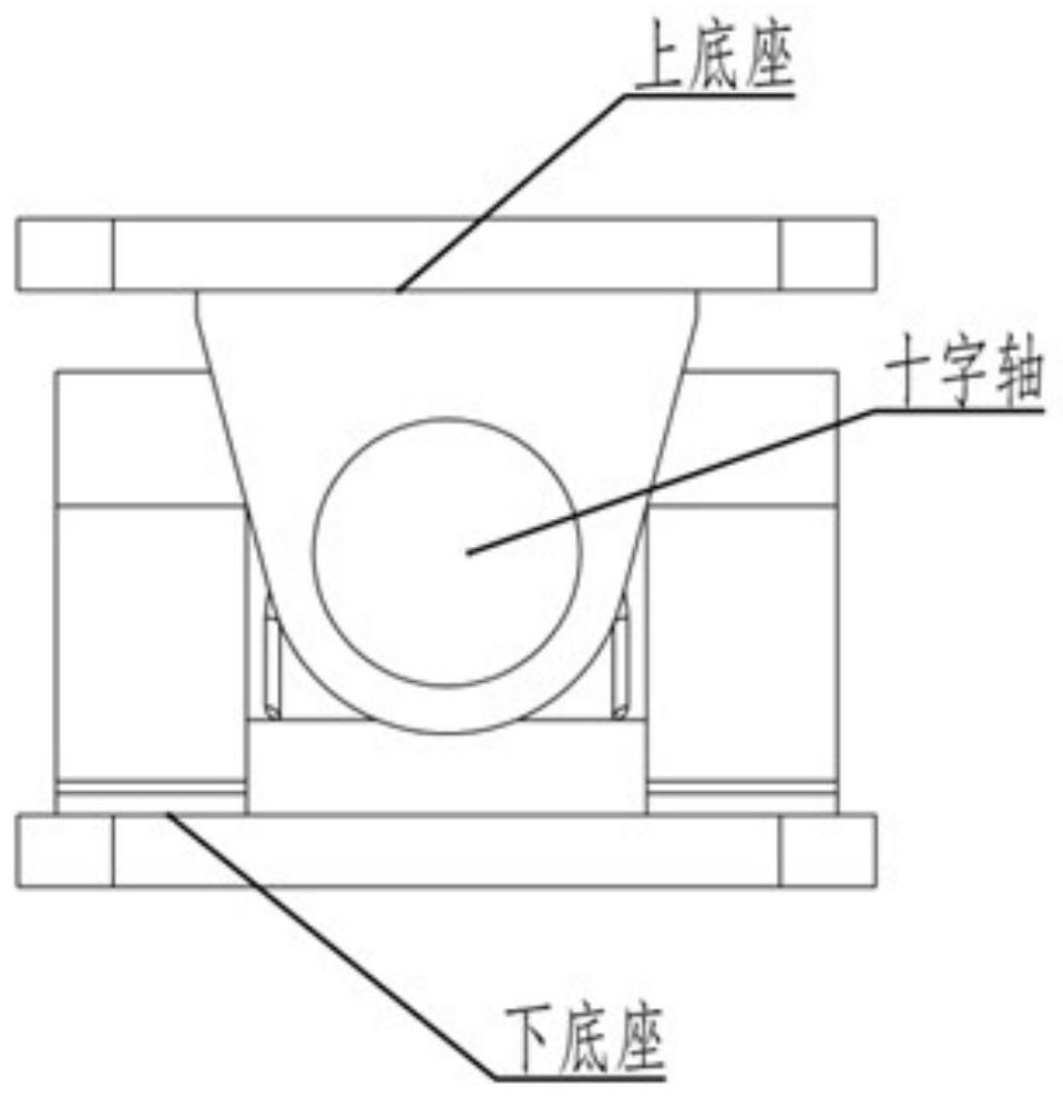
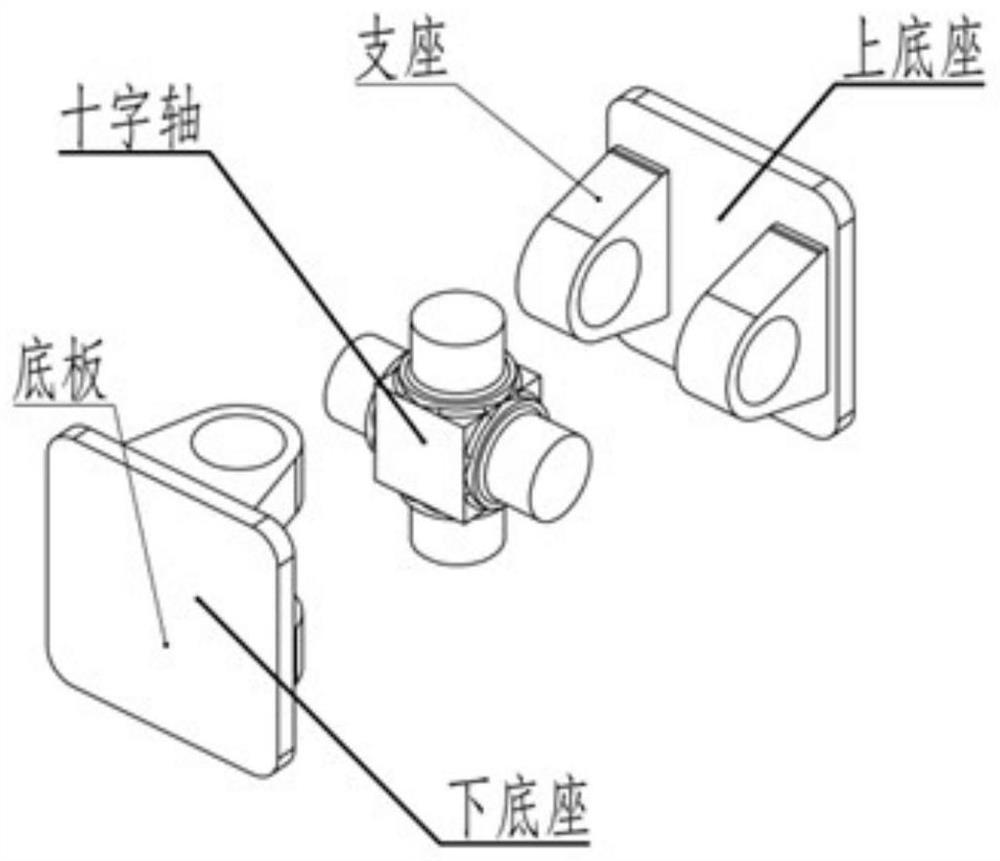
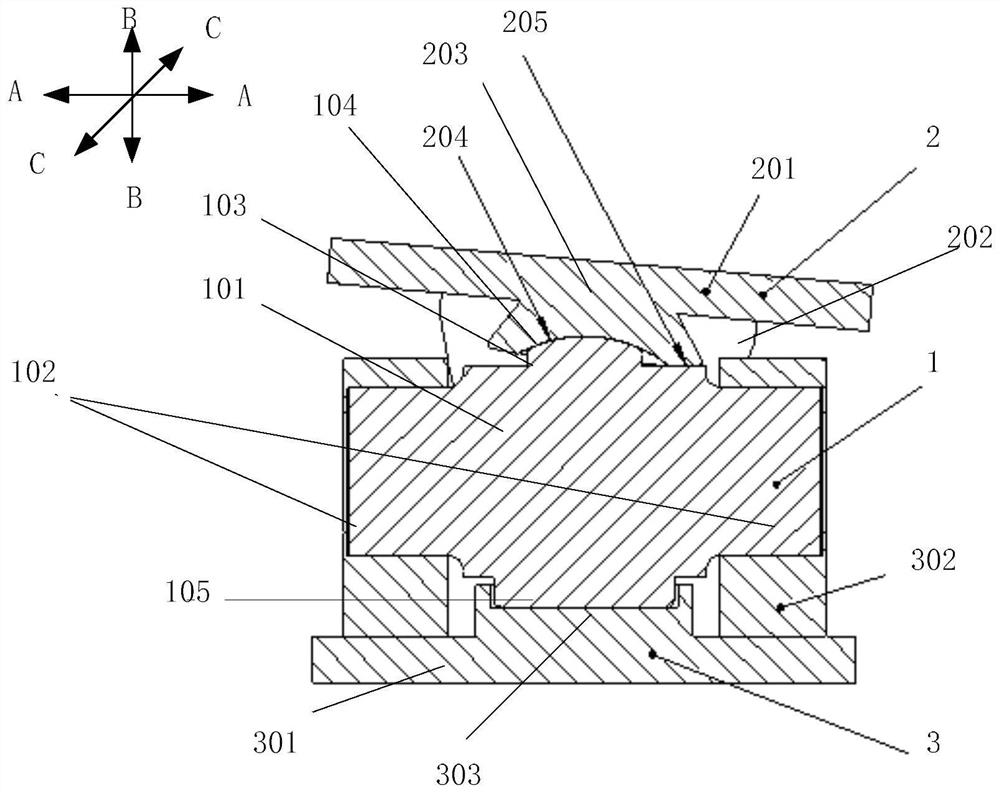
[0012] The technical idea of ​​the present invention is to provide a three-bearing force-bearing cross shaft gimbal to overcome the figure 1 and figure 2 There are flaws in the presented gimbal. Such as image 3 As shown, the embodiment of the present invention provides a three-bearing force-bearing cross shaft type gimbal, including: a cross s...


PUM


Abstract

The invention provides a universal joint pin type gimbal seat with three bearings for bearing force. The universal joint pin type gimbal seat comprises a universal joint pin and two bases connected with the universal joint pin; the universal joint pin comprises a universal joint pin body and two supporting shafts arranged on the universal joint pin body in an orthogonal mode, middle supporting parts are formed on the two side faces, not provided with the supporting shafts, of the universal joint pin body, and guiding faces protruding outwards are formed on the middle supporting parts; and the two bases are of the same structure and are rotationally connected with the two supporting shafts respectively, each base comprises a base plate and two supports symmetrically arranged on the base plate, the two supports are connected with the two ends of the corresponding supporting shafts respectively, a middle sliding part is formed between the two supports, and sliding faces matched with the corresponding guiding faces are formed on the middle sliding parts. The two supports and two half shafts of the corresponding supporting shafts are matched to form a first cylindrical sliding bearing and a second cylindrical sliding bearing respectively, and the middle supporting part and the middle sliding parts are matched to form a third cylindrical sliding bearing. Force can be directly transmitted, and the bearing stability can be improved.

Description

technical field [0001] The invention relates to a gimbal, in particular to a three-bearing force-bearing cross shaft type gimbal. Background technique [0002] As the hub for transmitting the thrust of the launch vehicle engine to the rocket body, the gimbal needs to have the dual functions of bearing and swinging at the same time. The cross-axis gimbal is usually suitable for rocket engines with a thrust of 50-100 tons. The upper and lower sides of the gimbal are respectively connected to the frame and the thrust chamber to transmit thrust, and the engine thrust vector can be adjusted in any direction through the two-way swing of the mutually orthogonal cross axes. [0003] The existing cross shaft type gimbal usually consists of three parts: an upper base, a lower base and a cross shaft. Both the upper base and the lower base are composed of a bottom plate and two supports, such as figure 1 and figure 2 shown. One shaft of the cross shaft is respectively installed with...

Claims


Application Information

Patent Timeline
Patent Type & Authority Applications(China)
IPC IPC(8): F16C11/06
CPCF16C11/06
Inventor 不公告发明人
Owner 北京星河动力航天科技股份有限公司
Why Eureka
Try Eureka