Rope cartridge gun

A technology of rope bullets and projectiles, applied in the field of rope bullet guns, can solve problems such as being vulnerable to injury, and achieve the effects of simple use, easy portability, and light weight

Pending Publication Date: 2021-09-28
北京拾壹德圣科技有限公司
View PDF0 Cites 0 Cited by
  • Summary
  • Abstract
  • Description
  • Claims
  • Application Information

AI Technical Summary

Problems solved by technology

[0002] At present, relevant personnel are vulnerable to injury during the arrest process, so a small, portable, and simple-to-use device is very necessary for the work of relevant personnel

Method used


Image

  • Rope cartridge gun
  • Rope cartridge gun
  • Rope cartridge gun

Examples


Embodiment 1

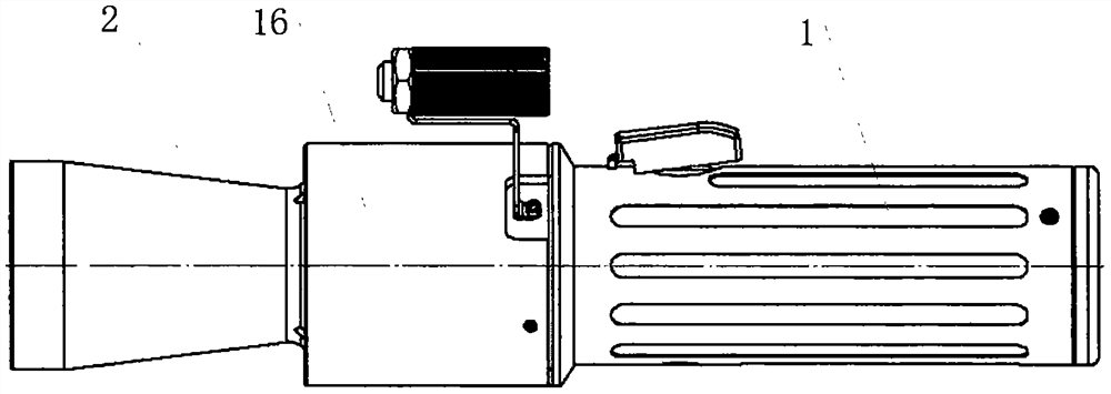
[0039] Such as figure 1 As shown, a rope bomb gun includes a trigger 1 and a rope bomb assembly 2, and the rope bomb assembly 2 is installed at the front end of the trigger 1 through a quick-change mechanism 16.

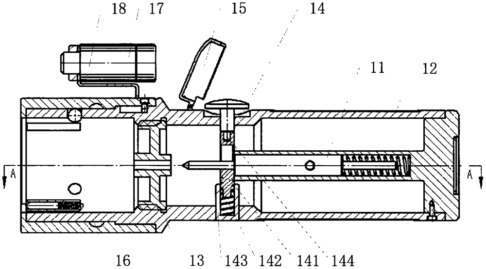
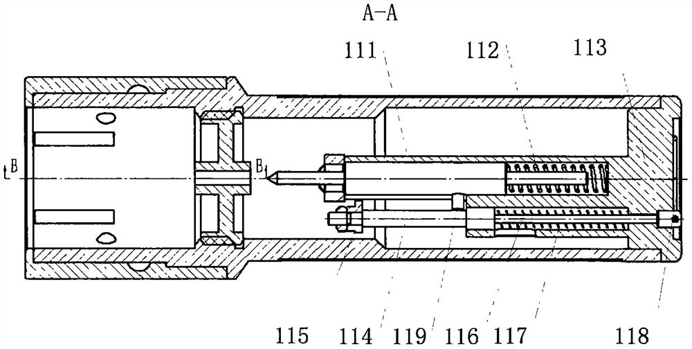
[0040] Such as figure 2 As shown, the firing device 1 includes a firing pin assembly 11 , an outer cylinder 12 , a firing pin blocking cover 13 , a trigger assembly 14 , a safety cap 15 , a quick change mechanism 16 , a laser sight 17 , and a sight bracket 18 . The firing pin assembly 11 is installed inside the tail end of the outer cylinder 12; the firing pin blocking cover 13 is fixed on the front end of the outer cylinder 12 by threads; the trigger assembly 14 is fixed inside the outer cylinder 12 and is located at the front end of the firing pin assembly 11; The shaft is hinged with the outer cylinder 12 and is covered above the trigger button 144 of the trigger assembly 14; the quick-change mechanism 16 is located at the front end of the trigger 1 for quick co...

Embodiment 2

[0050] Further as a preferred embodiment, such as Figure 15 shown, combined with Figure 9In contrast, on the sidewall of the outlet of the acceleration channel 3011 of the rope bomb housing 301 of the rope bomb assembly 3 and the front end of the traction head 302, no pin hole is set, and the shear pin 204 is not installed. After the nail bullet 209 of the rope bomb assembly 3 is fired, it pushes the piston 205 to move when gas is generated inside the rope bomb shell 301, and the piston 205 drives the pulling head 302 to accelerate, and pushes away the end cover 208 at the front end of the rope bomb shell 201 , until the traction head 302 completely breaks away from the acceleration channel 3011 of the rope shell 301, the traction head 302 accelerates, and then drives the rope 203 to continue flying to the target, and finally binds the target.

[0051] The other specific implementation modes of this example are the same as those of the first embodiment.


PUM


Abstract

The invention relates to an instrument, in particular to a rope cartridge gun. The rope cartridge gun comprises a percussion device and a rope and cartridge assembly, and the rope and cartridge assembly is connected to the front end of the percussion device by means of a quick-change mechanism of the percussion device. During use, a trigger button mounted on an outer cylinder is pressed, the trigger button drives a trigger to release a firing pin, the firing pin impacts a cartridge body at the tail end of the rope and cartridge assembly, high-pressure gas is generated in the rope and cartridge assembly after the cartridge body explodes, two pistons in the rope and cartridge assembly are pushed to move at a high speed in two acceleration channels of a rope and cartridge shell correspondingly, the pistons drive two traction heads and a rope connected to the traction heads to fly to a target at a high speed, and the rope is quickly wound around the target after making contact with the target to firmly bind the target. The rope cartridge gun is the instrument, the related personnel can remotely finish a capturing process, the safety of the related personnel is guaranteed, and the rope cartridge gun is simple in use process and convenient to carry.

Description

technical field [0001] The invention relates to a device, in particular to a rope shot gun. Background technique [0002] At present, relevant personnel are easily injured during the arrest process, so a small, portable, and simple-to-use device is very necessary for the work of relevant personnel. Contents of the invention [0003] In order to solve the above problems, the purpose of the present invention is to provide a small size, easy to carry, simple to use rope gun. [0004] The technical scheme adopted in the present invention: [0005] The utility model relates to a rope bullet gun, which comprises a trigger and a rope bullet assembly, and the rope bullet assembly is installed on the front end of the trigger through a quick-change mechanism. [0006] The firing device includes a firing pin assembly, an outer cylinder, a firing pin blocking cover, a trigger assembly, a safety cap, a quick change mechanism, a sight, and a sight bracket. The firing pin assembly is ...

Claims


Application Information

Patent Timeline
Patent Type & Authority Applications(China)
IPC IPC(8): F42B12/68F41F1/00
CPCF42B12/68F41F1/00
Inventor 杨建世裴吉星白英博
Owner 北京拾壹德圣科技有限公司
Why Eureka
Try Eureka